Brake cylinder pressure cannot exceed the maximum EP valve setting of 55 lbs/sq in.
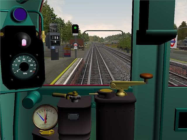
Right - if I understand the operation correctly, with a TV ratio of 2.5 the brake cyl balances with the train line at (near enough) 45psi. Here's a screenshot with the recent numbers implemented. Brake obviously Off/release. Gauge reads 0-140 in 20psi increments. Does it look "right"? (Ignore the blue needle - it's only there so I can monitor brake cyl pressure vs. decel rates).
Nice cab, huh? A tallented guy named Darren gets all the credit. I'm just tweaking the physics.
BTW - did the sequence light (right above the speedo) get lit when in full parallel motoring? if so, I can implement that feature. If not, please advise what it should do and I'll try and replicate.
A quick plot with Excel suggests a train line drop of 18psi, yielding 45psi at the brake cyl (2.5 TV ratio) and leaving 47psi in the train line. So full service (EP) would be a train line drop of 65 to 47. Ring any bells, or am I totaly out to lunch?
Post-traumatic déjà vu disorder: The feeling one gets after one has experienced trauma before it happens.
Wow - lower than I'd expected, as I thought 110 was a UK standard (vs. 140 in USA). OK, from those figures I can calculate the cyl pressure for max brake (= train line drop times TV ratio). Thank you sir! I'll plug in those numbers and see if I hear any hissing... ;D
Thanks again CSLR. I now have it all functioning (except graduated release due to yet another "undiscovered feature" courtesy of Kuju ). Values are currently: Main Res max = 110psi. Recharge at 90psi (may be low but functions). Train pipe max (nominal) 80psi. Triple valve ratio 2.5. Brake cyl pressure for max brake = 57psi. So the train pipe drop and cyl pressure rise to meet at 57psi (drop of 22.8 in the train pipe multiplied by the TP valve ratio). Seems to work fine and the needles do the right things. I'm now fine-tuning the brake force for the differing DM and Trailer weights.
If anyone knows any of those values to be wrong, please let me know. I've now (finally) sussed all the relevant MSTS parameters and their relationships and can adjust as needed. There are a few details left like the compressor charge rate, apply/release rates, etc. that will also be tweaked as I test it and learn more. Sadly, it does appear that the Kuju implementation of graduated release may be totally broken, but I'm still plugging away at it...
Best, Jimi
Post-traumatic déjà vu disorder: The feeling one gets after one has experienced trauma before it happens.
Understood and agreed re "looking out of the window", however given the MSTS cab display the gauge will be in your peripheral vision and I'd like it to at least reflect expected operation. Besides, there's always a "rivet counter" somewhere, ready to pounce on inaccuracies ;D Maybe when I get it working reasonably I'll take a quick FRAPS video, so you folks can see if the operation "looks right". Constructive criticism is always welcome, and I've had my share with the route and various trains, to the betterment of both. PP was always good at it ;D
Me: How's it look? PP: I dont see too much wrong with it. (pause) Mind you, I haven't looked closely yet.
Post-traumatic déjà vu disorder: The feeling one gets after one has experienced trauma before it happens.
...The EP on the 38ts has an infinite number of braking positions, but in practice would take forever to apply and release on a sim, so a number of notches would be better for ease of use.
We can do either notched or variable. With the variable, there is a parameter that defines how much effect a single keystroke has, thus if set appropriately, you wouldn't be "holding the key down" (key repeat) to get appropriate application. Partial release would also work using the same granularity.
I got to test the new cab and controls last night. It's "functional" bit needs a little tweaking. Do you folks happen to know the PSI drop on the black needle (train pipe) for the initial EP application ("Just on") and the total drop at full EP? I want to make sure we're using all the right values for the brake system. I can fine-tune the actual braking force afterwards. Red needle seems to behave itself and correctly report the res pressure. Compressor kicks-in correctly and re-charges, but I'm not sure if the values are right -- max res pressure and recharge pressure. Anyone know those also? Does a triple valve ratio apply? If so, ratio?
The "incentive" comment was tongue-in-cheek BTW. I'll certainly implement a version after we get the EP working right.
CSLR -- if you're indeed visiting my area I would certainly look forward to a chat over a cold one or two!
Thank you sir! Duly sorted. In essence the gauge now works and looks right, with only a few small tweaks left. Regarding the training material, should you have the spare time to do so (I stress, entirely at your convenience) I welcome such material with open arms. Partly as I'm inherently interested in such things, and partly as it helps to validate the 'virtual renditions' are as good as we can make them, within the usual Kuju limitations I can PM you an email addy if that would be appropriate.
Thanks again, Jimi
Post-traumatic déjà vu disorder: The feeling one gets after one has experienced trauma before it happens.
One more question for the experts... On the duplex brake gauge, what color was each needle, what function did each display, what was the scale range (numeric)?
It looks like we're very close to a real 38TS cab and controls. Just need to sort the brake gauge and then do a little road testing ;D
Thanks in advance, Jimi
Post-traumatic déjà vu disorder: The feeling one gets after one has experienced trauma before it happens.
Thanks all! I of course transposed EP and Westinghouse through my post. Brain thinking one thing, fingers typing another: I meant we CAN do EP, but not Westingouse AS WELL. I thought it was self-lapping and partial release. Thanks for confirming, and the extra details!! I know how to do that in MSTS. I actually implemented a good EP + blended Rheo in my original CO/CP MSTS offering. But the blended rheo and combined controller (CTBC) prevented partial release of the EP (don't ask -- blame Kuju). I fudged it to work in the V2.3 update and improved it for the D78.
One for you more senior experts, maybe. A guy on UKTS is implementing a real nice realistic cab for the MSTS 38TS. He's trying to implement a realistic brake system and I'm trying to help (I know how, but don't know exactly what we need to model). Thus, some key questions: Was it a lapped Westinghouse? Did it have partial release? What were the positions on the brake controller for (we do have a nice realistic controller with the detent positions)? Note, we can't implement the EP part as well as MSTS can't do 2 brake systems. Any and all info deeply appreciated!
Best, Jimi
Post-traumatic déjà vu disorder: The feeling one gets after one has experienced trauma before it happens.
Awesome stuff - thank you! Reminds me of some photos in Mr Agnew's 2 volume "Electric Trains". I got lucky recently and found a copy is very good condition. Amazing how some of the old control systems worked. Arc shields in a control pedestal!?!? <cringe> Bzzzt-crackle...
Electrical Safety 101 - Do not stand in a puddle near anything that hums ;D
/Jimi
Post-traumatic déjà vu disorder: The feeling one gets after one has experienced trauma before it happens.
A few thoughts provoked by yours... A monomotor bogie implies, of course, that the new motor could supply the same torque (tractive effort) as the two motors it replaces (assuming it has to provide the same performance for the same weight moved). It would likely be an AC motor - so does such a motor exist that can provide the oomph, be small enough to fit, and efficient enough not to get too hot? Can a small enough hypoid gearset be built so provide the needed gear ratio? Let's assume for sake of discussion the wheel size is as for D Stock, as is the requried gear ratio (although that would depend on the balance speed for the new AC motor needed, noted above). You don't need a laser for an accurate speedo. The refurb D Stocks already have GPS, which can provide more than enough accuracy - when it can see the birds. For 'dead' areas (tunnels?) why couldn't an accurate-enough wheel or transmission driven speedo be built? Or maybe an electronic speedo that 'counts' motor pulses (AC motor driven by chopper-type circuit and inverter) and knowing gear ratio and wheel size can calc the speed?
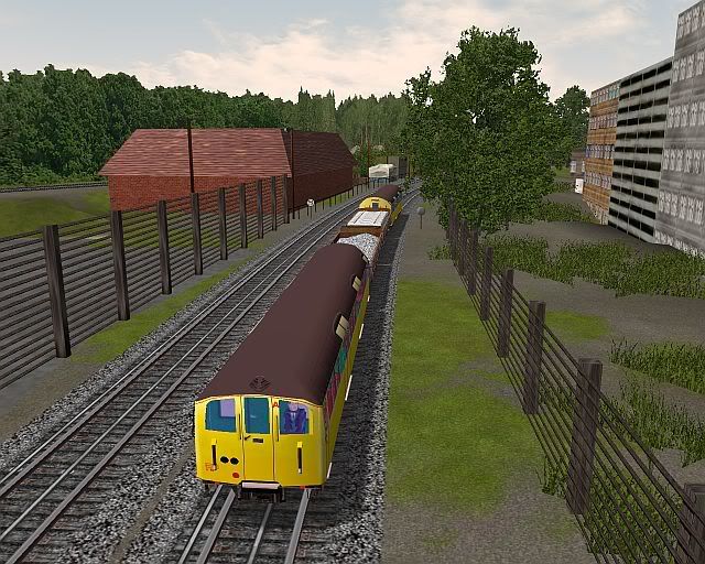
TubePrune & Colin - thank you for the additional info! The test I showed was mainly to test the 'virtual technology', and I felt my track circuit spacing and home signal placement was a bit off. Fortunately, my implementation allows positioning the 'detectors' at any point along the platform, and the homes are not limited by distance. I think my next test will be to try and replicate the homes approaching ACT EB from ECM down the bank. My signal diagrams show a 20mph speed test followed by homes. I'll get the positions as close to the diagram as I can and test if a 20mph approach results in the expected behavior (assuming virtual Picc trains aren't blocking both platforms ;D)
Based on your comments it seems the virtual representation is reasonable, and I think the flexibility is there to suit prototypical use at various locations. I'd just always wanted to add this feature to the virtual LUL signal set. My next challenge is to correctly signal Triangle Sidings - once again the sim is lacking in intrinsic capability and a little ingenuity will be needed.
I greatly enjoy trying to model LUL operations in the sim, and the kind support of you professionals is warmly appreciated.
Best to all, Jimi
Post-traumatic déjà vu disorder: The feeling one gets after one has experienced trauma before it happens.
(If this better belongs in the Sim threads, I apologize - I put it here as it's a follow-on to my original question, and I felt the experts might spot it here). BTW Colin - fully understood, and thank you! I plead a senior moment
I always felt this was possible in MSTS, with a little ingenuity. I based my implementation from the description in TubePrune's site:
(Click on the multi-home title at the top of that page to get to the relevant segment of the description.)
The homes each go red as the train passes (their own block being occupied), and then clear as the train progressively departs the platform.
So to test it out in MSTS, I designed and created the required components. 4 of them are hidden - 3 "track circuit detector" items, places at the platform edge and at 1/3 and 2/3 the way down the platform track, per the TubePrune diagram; and a "track circuit repeater" item that the 3 home signals test to determine what track circuits (A, B, C) in the platform are occupied. The homes (A/B/C) should clear to green in sequence as the train ahead departs the platform as each of the track circuits clears. As the video shows (see URL below) it looks easy - in fact there's a bunch of logic going on behind the scenes, as with the real thing. I approached the A home slowly and waited for it to clear, then I held about 15mph so as to approach the B and C homes as they cleared as the train ahead departed the platform. It appears to me to be prototypical behavior. Note that it is the train AHEAD that is causing the homes to clear, not our train! Note also the A/B/C plates on the signals showing their function. The example location (part of the extension to HSK etc. that Eddie is working on) was purely for test purposes.
Click the URL below (select 'save' to get it to your PC, then view it). It's about 11MB and runs about 2 minutes. If you have a fast enough connection, you can open it directly and it will play in Media Player.
MSTS District Line Video:
The video shows us from the cab of a train and another train ahead of us. It doesn't show the train ahead passing the homes on its way into the platform, but they do behave correctly in that respect. We then follow as the signals allow our progress. Did I get it right?
Assume for purposes of discussion and explanation that there are 3 multi-homes (A, B, C), with each reading a track circuit that encompasses a third of the platform length (I suspect that 'C' also reads the starter overlap). As a train enters the platform ('A' track circuit) the 'A' home would go red. Would the B and C homes also go red at that point, or do they go red in sequence as the train progresses into the platform? I know they clear in sequence, but am not sure of the logic setting them to red (realizing that they also must each go red if 'their own' block is occupied). All wisdom gratefully received!
As you might imagine, this is so I can finally realize one of my 'holy grails' of implementing this in MSTS. I have the clearing logic working - just need to make the 'red' logic prototypical.
Darren - I have a copy of the cross-sectional loading gauge for tube stock, which shows dimentions and distances from the walls, etc. from which you could deduce the 'bore' and other info including rail locations. Not sure if that would help. Email me if so, and I'll mail it to you.
/Jimi
Post-traumatic déjà vu disorder: The feeling one gets after one has experienced trauma before it happens.
Got it! I had assumed that the "a,b" nomenclature was similar (if not the same) as for multi-home signals, and I'm familiar with how those are wired and operate (thanks to TubePrune et al). I was also checking other converging junctions to see if this was a common arrangement. Neither HLJ EB (DL/Picc merge) nor EB Slow at ACTN (DL/Picc flyunder EB slow merges) have a/b signals; however these examples are both within 20mph PSRs, so speeds will be low and the need for overlap protection is greatly reduced. Is it therefore the 'norm' to have a/b signals in convergence areas where speeds would be higher? Just curious.
Thanks, Jimi
Post-traumatic déjà vu disorder: The feeling one gets after one has experienced trauma before it happens.
Pardon if I'm wrong or confused, but per my 1963 chart WK1 is on the EB slow from CP. Whereas WK11(ab) is on the RMD EB road, with the repeater (RWK11a) - which is I think the repeater SB is refering to - being just before the flyunder. Which makes me wonder how/when WK11 does clear. Presumably the route has been set from GUN to TG and (per SB's observation) the train is approaching RWK11. This is the short section annotated "DD". Similarly, I'd expect WK1(ab) to clear if the route was set for a train from CP. I do recall a video showing a train held at WK11b on the up-bank after the EB flyunder, so I'd assume the route had been set earlier for a CP EB train. Who gets the perferential treatment - a GUN train or a CP train? My gut would say WK11 would only clear if (a) a train was approaching RWK11a (i.e. imminent train wanting to merge onto the EB Slow) and route through WK1 was not already set. Also what's the sequence for WK11a and WK11b? I see there's enough overlap between then (397') to fit a train. Same question regarding Wk1a and WK1b. Pardon the intrusion from a novice - I'm still trying to learn signals operation so I can model it realistically.
Colin -- me going for I/Op? Virtual T/Op maybe I'm just enjoying puzzling this out. I actually discovered the train out of 21/22 sidings fouling 16 points in our simulated version, and then went to look more closely at the chart to see if we got the sim correctly to scale. Seems we're close ;D I then wondered as to the implication, which you've confirmed.
Re the EB train going to 28 siding... As a direct EB-WB road move is not possible (single slip), then I conclude a reverse off the EB via WF6 to (say) siding 23, then WF32 route 2 to the WB wrong road, then WF26 clearing for siding 28. Seems a 'mirror' move for a WB train into siding 25/27 reversing to the EB wrong road via 21/22 sidings is also possible.
As you note, many combinations are technically doable! That was in part the root cause of my questions as to what moves were 'usual' or required. This has been most entertaining and informative. My thanks to you all.
One final question, prompted by the service diagram photo. It seems that a lot of shunt sigs on the diagram are 'illuminated'. How is a shunt on/off depicted on that diagram? Red/lit if off? Red on vs. green off?
Thank you for the additional info gentlemen! I had been further pondering the achievable moves involving WF4, and realized the s27/s25 to s24 move was possible as AET described. Is that early move done to make the train 'more convenient' to enter service on the EB?
Further examination of the chart suggests that a train exiting s21/22 onto the EB would likely still be fouling the 16AB points when it reached the nominal stop point for the EB platform (distance from stop point to 16A points looks to be close to 85m) and thus not be fully in the platform. Would the train then continue to Fulham Broadway before being able to enter service?
Finally, if a train arrived on the EB and was intended to then stable in s21 or s22 would it draw forward so as to clear 16A (say to just shy of 15A points) so it could accept WF4 route 1/2 and then reverse? Or do trains on the EB only use 23/24 (or 25/27)? Logic (easier, less disruptive moves) suggests trains on the EB would use s23/24/25/27, and those on the WB could use 21...24 (and 28 or 29) as available.
Despite what seems physically possible, I'm just curious as to what is normally done. As many know I'm fascinated by the operational and technical side of things - and I'd also like our team's simulation of same to be realistic.
Thanks in advance, Jimi
Post-traumatic déjà vu disorder: The feeling one gets after one has experienced trauma before it happens.
I've been studying the charts for the shunt signals at PGN (notably the multi-path ones) and I think I have them all figured out - except for one (WF4). Here's my take, and I'd appreciate feedback from the experts as to my accuracy. IIRC, the number displayed on the theater will show the possible routes from "left to right".
WF9 - 4 ROUTES off WB - SIDINGS 21, 22 (via 18 slip), 23, 24 (via 22A/B points) WF6 - 2 ROUTES off EB wrong road - SIDINGS 23, 24 (via 24 slip) WF29 - 3 ROUTES off S21 - EB, WB, S29 WF30 - 2 ROUTES off S22 - EB, WB WF32 - 2 ROUTES off S23 - EB, WB WF33 - 3 ROUTES off S24 - S31, EB, WB Now the one I'm unsure of...
WF4 - 3 ROUTES off EB wrong road - S21, S22 (via 16A/B points), and (here's the guess) EB to WF6
So the one I'm unsure of is route 3 on WF4. The only path I can see (other than across 16A/B) is to remain on the EB wrong road as far 'back' as WF 6, which would then show 1 or 2 for S23/S24.
Confirmation and/or correction greatly appreciated. Also given the points are clearly single-slips, reverse moves seem only possible via the 21...24 sidings (easier WB-EB). Is that also correct?
I'm enquiring for purposes of accurate 'simulation', but as my question relates to real DR infrastructure and procedures, I felt it would be appropriate in this topic.
Thanks in advance, Jimi
Post-traumatic déjà vu disorder: The feeling one gets after one has experienced trauma before it happens.
Not a prayer! If I have to keep up with every change the west end of the line will resemble 1990 and the east end 2010! I've been 'backtracking' periodically add changes (e.g. add speed boards, change signals) but there's a limit...
Post-traumatic déjà vu disorder: The feeling one gets after one has experienced trauma before it happens.
Bow EB to Bromley-by-Bow appears to be 1/51 for the first 50m, then 1/38, 1/39, 1/40 for the remainder of the climb to the 20 PSR at about the 380m point. Interestingly, I also note a rise of 1/38 for the final 250m climb into Whitechapel on the WB. However, the worst climb/drop I see on the DL is leaving Barking WB (pfm6 ) to East Ham, with a 1/40 climb on the flyover to signal FF6 and then a 1/35 drop during a 400m section. I just watched the video of that section to confirm and the downhill 1/35 resembles a rollercoaster to me Didn't realise it was that steep from previous video viewing.
Thanks, that's possible. I'll look at the video again and see if that fits. It seemed to me there was a bunch of construction-type materials in the yard. Here's my virtual version, if that jogs any memories
I figure one of you eagle-eyed guys on the front has to know this. There's a very distinctive building on the section between Kew Gdns and Richmond. Going south, it's on the left after GB15 and bridge 31a about next to the 35 PSR as you enter the curve. It's a rectangular brick building with an odd-shaped flat roof. There appears to be a signboard with a green background visible from the line, but I can't make out the wording on any of the videos I have. I'd appreciate knowing the name, or the nature of the business. As it's so distinctive I'm modeling it in the virtual DL and would like to include an "appropriate" sign on it.
Thanks, Jimi
Post-traumatic déjà vu disorder: The feeling one gets after one has experienced trauma before it happens.
Understood gentlemen, and thanks! I'll have to simplify that a touch for the sim, but will note the correct detailed process in the related readme file.
Post-traumatic déjà vu disorder: The feeling one gets after one has experienced trauma before it happens.
I think this has been discussed, but I can not find it. Apologies if so. I'm designing a dastardly activity for the virtual DL...
Hypothetical: Assume you come to a red signal (happens to have an 'arbor light too, not at all dissimilar to WM20/21 ;D ) The red light goes out, but no green shows (dead bulbs?), and possibly no arbor lights either. The lack of red (it was lit) suggests it's clear, but it might be stone dead. State of trainstop undetermined. What's the procedure? Do you need to contact the Line Controller? Do you call signaler to get authorization to 'pass under rule', treating it as a failed signal? In such a case, what do you tell/ask the signaler? What does he tell you? Example phone or radio dialog would be most instructive.

 ).
). I meant we CAN do EP, but not Westingouse AS WELL. I thought it was self-lapping and partial release. Thanks for confirming, and the extra details!! I know how to do that in MSTS.