DrJimi
Virtual District Line construction engineer and arborist
Posts: 365
|
Post by DrJimi on Aug 25, 2005 14:22:09 GMT
Progress on temporary hold due to it being Summer (outdoor activities take precedence :-) I'll be getting back to it in about a month.
Status is that the Richmond road is going very well, despite continual fights with the RE and MSTS dislike of object density. Goal is to finish that section ASAP. I think it's my favorite part of the line to drive - crossing the river is cool. Next will be to continue adding scenery EB toward HAM. I may well release it at that point, just to give folks a chance to try it out. The tracks are all in as far as ECT (plus OLY), but the Wimbo section metals remain to be laid. I also have to slightly re-locate Lille Bridge depot - it's built, but in slightly the wrong spot, and not correctly oriented.
|
|
DrJimi
Virtual District Line construction engineer and arborist
Posts: 365
|
Post by DrJimi on Mar 31, 2005 13:58:17 GMT
The strange thing is, I actually thought the same thing one evening when I was motoring in to check the stop point, etc. And an unbidden voice intoned in my head "Mind...the gap!". Not so much a gap, as a chasm ;D
The idylic greenery will be subdued somewhat, after I add the sooty ballast, weeds, scrub, etc. While I strive for realism I do, however, draw the line at litter-strewn tracks and graffitti. You'll have to imagine those..
The view pictured is unusual for me to see, because I usually place the platform(s) first when building a station. This time, there were some critical 'landmark' objects to site first, so the platforms would then be correctly located relevant to those (e.g. Chis High Rd and A3000 overpasses, PSRs, signals, BSI, car parks, etc.). The LUL pfm end barriers are only in place to mark the intended pfm ends to assist in model sizing and placement. I'm fortunate to have some good detailed pictures for this branch, so you can expect to see some nice Silverlink and other related signage.
I'm finding this branch fascinating to build and drive -- despite a certain east-end I/Op opining to me that the novely would wear off if I had to drive it a few times. A day. For years ;D
|
|
DrJimi
Virtual District Line construction engineer and arborist
Posts: 365
|
Post by DrJimi on Mar 31, 2005 2:36:51 GMT
Alan - thank you! As you all likely know I'm trying hard to capture the spirit of the line. So a comment like that from a LUL professional makes me feel good. Of course, SB (in lieu of PP) will shortly be along to point out that one of the bushes is 0.173ft too far from the PSR sign. Actually, PP would likely say "I don't see too much wrong with it. <pause> Mind you, I haven't looked closely yet"  Dave - thank you for your hospitality. I'll do my best to provide something (hopefully) interesting periodically ;D Thomas - no problem, and thank you for your courtesy. Best to all, Jimi (and it's finally getting warmer here! I must get out more...) |
|
DrJimi
Virtual District Line construction engineer and arborist
Posts: 365
|
Post by DrJimi on Mar 30, 2005 2:51:20 GMT
Going fine. Here's a pic of Gunnersbury station - missing an obvious critical part.  That's what I'm working on right now. Not only do I have to build the platform and the attached overhead walkways and booking hall, but I have to create the right signs (NR, not LUL), canopies, etc. I'm also creating the needed extra 3-aspect signals for this section. Please don't ask when it will be done - this is a hobby, remember? When there's something worth showing I'll post news here (if that's OK with Dave) and also likely on UKTS. |
|
DrJimi
Virtual District Line construction engineer and arborist
Posts: 365
|
Post by DrJimi on Mar 24, 2005 23:23:55 GMT
Guys, please - your enthusiasm is great, but relax a little. I'm building it as a part-time hobby for the enjoyment of doing it. It's not a commercial enterprise with a massive team and big $$$, so there's no schedule. However its very likely I'll release something this year, but I don't know how much will be complete. All I can tell you is that what will be there will be good, because that's my only real goal. It's likely that people who aren't familiar with MSTS route building don't realize what's involved - so in the near future I'll post a brief description, likely relating to some screenshots of the Richmond branch development now underway. Hopefully that will at least explain why it takes me so much time to do it. On a related note, there's a person on UKTS claiming to be building several LUL lines, has "almost finished the Met" and has been working on it for "months". Months? If I could work at his apparent pace, by now I'd have the whole combine finished  So don't be misled by some who seem to claim that routes can be built in no time flat. The odd few that have been, usually look like it Again, thanks for the enthusiasm, it is appreciated. The response to the D Stock was amazing - over 500 downloads so far. But, it is still a hobby  Best, Jimi |
|
DrJimi
Virtual District Line construction engineer and arborist
Posts: 365
|
Post by DrJimi on Mar 22, 2005 23:21:58 GMT
Normally I put up a new set of pictures as a section of the line becomes completed (stations built and all scenery in place). I may make a change this time and take some shots as I build the Richmond branch. Some parts are complete, but there's still 3 stations and a lot of buildings and other scenery to do. However, it may be interesting to some to see "how it's done". FYI - the reason for the seemingly long delay is in part due to me totally re-doing the "DEM" data for the entire line. This relates to the ground contours and height data. It became obvious early in the RMD section that all was not well. I was fortunate to obtain the latest NASA Shuttle topographical mapping data (sadly still only 90m resolution) and use that. All now looks as it should. Of course, having re-set the ground height and gradients, a lot of sections of trackwork had to be re-sculpted in terms of the cuttings and banks, re-excavating tunnels, etc. This isn't a quick nor easy task, but I was determined to get it right once and for all. I'd expect some new photos within a month. There's a few buildings on the bank of the Thames near Kew that I'd better put in place before too long Best, Jimi |
|
DrJimi
Virtual District Line construction engineer and arborist
Posts: 365
|
Post by DrJimi on Mar 16, 2005 1:43:40 GMT
You are too kind, sir - although I'll admit I'm pleased with how that section of the line has progressed. To give credit where it's due, I'm now using a new set of tree objects developed by a kind person from Czechoslovakia. Those trees seen above are actually just simple cruciform shapes, but the texturing is so good it's hard to tell, even close up. To me they look quite realistic - especially when 'sprinkled about' as nature tends to do. I've also tried to mimic certain noticeable trees that caught my eye in the cab videos. To me they're kind of a subconscious landmark, as opposed to buildings like the BSI center near GUN that are obvious. Below is one more screenshot of the GUN-KEW section (under development), showing the Kew Rail Bridge, the Thames and Oliver's Island (and signal GB10). You 'll notice the vast quantity of nothing on either side of the river, which will change shortly. Several of the team are most concerned that I accurately model certain public houses that are on the east bank, and have supplied excellent detailed photographs of the establishments to aid me in that endeavor. After all the 'research' they obviously undertook, I would hate to disappoint them ;D 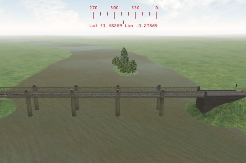 Best, Jimi (Virtual District Line track, bridge and pub constructor) |
|
DrJimi
Virtual District Line construction engineer and arborist
Posts: 365
|
Post by DrJimi on Mar 15, 2005 21:11:58 GMT
SB has summed up progress very well. The lines from TGN to RMD are in place and I'm now steadily putting in the scenery, foliage and stations. The section from TGN to GUN is about complete -- placing the line-side buildings and trees to my satisfaction took about 1 week! The TGN and GUN stations are now being built, and Kew Rail Bridge (and the river) are in place. This is certainly an interesting part of the line, both to drive and for its scenery. Here's part of the line between TGN and GUN:  NOTE: Yes, I was speeding slightly; and now realize how hard it is to drive and take photos at the same time - even virtually. And, yes, I forgot to turn on the Saloon lights. Mea Culpa. I'm am, however, delighted how the D78 train has come out. The final test kit is now in the hands of the Beta test experts (including two well-known D78 I/Ops), and - baring any last-minute show stoppers - I'd expect release within about a week. I'm currently finishing a 14 page illustrated Operator's Guide for the train, which will be included in the release kit. I'm greatly looking forward to the reaction to a couple of surprises we've put into the train Best to all, Jimi (Virtual District Line builder and arborist) |
|
DrJimi
Virtual District Line construction engineer and arborist
Posts: 365
|
Post by DrJimi on Feb 27, 2008 23:38:23 GMT
Darren,
WA Agnew Vol 2 p 405 notes they had 4 notches (actually 5 counting 'off'). These being:
0. Off
1. Shunt (Series connected)
2. Series (with accelerating relay allowing up to about 1/2 speed)
3. Parallel with resistance in circuit
4. Parallel with accelerating relay allowing up to full speed.
It further refrers to Vol 1 p 77 which describes the Metropolitan Vickers Type OA-3-B controller. It appears 'off' is at 3 o'clock (per your screenshot) and logically, looking at the limit stops, parallel is at 9 o'clock. The book does not, however, explicitly state the 'clock' of the other 3 notches. But looking at the photo of the controller's internals suggests they are equally spaced (i.e. 45 degrees per notch). I would bet TubePrune knows for sure.
Not sure on the brake handles, as I've only modeled a combo EP/Windyhouse thus far (38TS), but a Windy controller ought to have Charge/release, Hold and Apply at a guess (no idea as to positions and extent). I believe I know how to model the 'physics' of both brake systems, but we'll need the input from experts as to the control handle(s) operation and positions.
/Jimi
|
|
DrJimi
Virtual District Line construction engineer and arborist
Posts: 365
|
Post by DrJimi on Sept 10, 2007 1:48:49 GMT
Thanks TP! We're close then - I get about 25mph at the 5-car board, and once had it up to almost 50mph, on a downgrade with a following wind ;D
I'll post new pics once we've 'fixed' the dest blind. Headcode lights are done for several destinations. Looks cool seeing one (AI train) approaching and realising where its going (in theory).
|
|
DrJimi
Virtual District Line construction engineer and arborist
Posts: 365
|
Post by DrJimi on Sept 3, 2007 0:19:22 GMT
|
|
DrJimi
Virtual District Line construction engineer and arborist
Posts: 365
|
Post by DrJimi on Sept 2, 2007 19:40:15 GMT
After some tweak and test I think we're close. I based the physics on our 59TS but increased the acceleration below 20mph. Thanks to Dstock7080 (History thread) we also discovered the color of the 'liquid speedo'. Normally I'd post screenshots to the sims threads, but I hope it's relevant here. (BTW - ignore the digital readouts - they're purley for monitoring performance while testing). APPROACHING HLJ EB 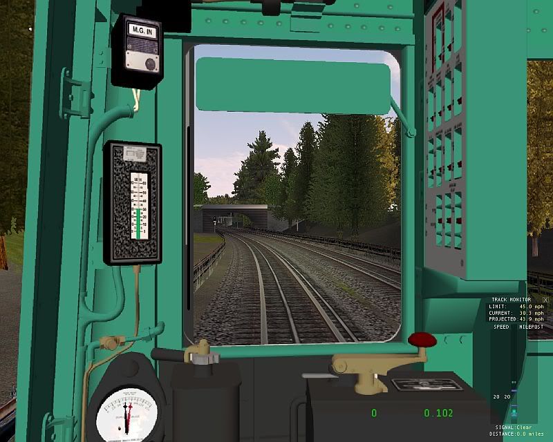 ARRIVED AT EALING COMMON 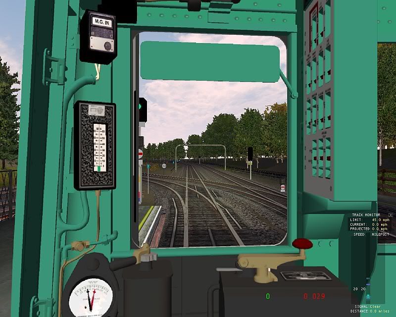 I suspect our speedo may be a tad more accurate than the original ;D Is the liquid color about right? Thanks, Jimi |
|
DrJimi
Virtual District Line construction engineer and arborist
Posts: 365
|
Post by DrJimi on Sept 1, 2007 12:48:10 GMT
Does anyone have first-hand or anecdotal knowlege about the performance of the R49? Comparisons to other period stock (e.g. COCP, 59TS) would be ideal. We're now glueing together our MSTS R49 and I'm at the point of tweaking the physics. From "Steam to Silver" I see that all cars are motored, but each with only 1 motored axle. I have dimesions and car weights correct (and also weight/drag, etc. factors). I'm trying to fine tune acceleration and braking in particular.
Some clues that would really help are things like:
Speed (from stand) at the 6-car mark (help me figure acceleration)
Time or distance to 30 or 40 mph
Distance from 30mph to stop (within its own length?)
Any and all info, estimates and educated guesses welcome!
May thanks, Jimi
|
|
DrJimi
Virtual District Line construction engineer and arborist
Posts: 365
|
Post by DrJimi on Jun 26, 2007 21:43:58 GMT
This is my original website. I'm sorry TP, I was unaware else I would have given you due credit. I did sense the author 'knew his stuff'. My hat's off to you once again! Artery - I have found 3 copies of the '38 book available - ranging from $57 to $164! I'm tempted... |
|
DrJimi
Virtual District Line construction engineer and arborist
Posts: 365
|
Post by DrJimi on Jun 26, 2007 16:01:19 GMT
Well worth the money Darren! I lucked into the 2-volume set in excellent condition from a bookstore in New York city for a 'reasonable price'. As an electrician you will drool over it (as I do). As TP notes, there are circuit diagrams as well as illustrations and detailed explanations. I'm very tempted to try and build a current-limit driven RPA setup for a small motor - just to see/hear it work ;D I can still hear the notching relay sounds in my mind, despite my last trip on LUL was likely over 30 years ago. I'd rate Mr Agnew's hefty tome as likely the definitive reference work on the subject. EDIT: Found some useful references about DC traction motor control that include notes on notching relays and RPAs: www.railway-technical.com/elec-loco-bloc.shtmlwww.railway-technical.com/tract-01.shtml/Jimi |
|
DrJimi
Virtual District Line construction engineer and arborist
Posts: 365
|
Post by DrJimi on Jan 13, 2007 21:02:00 GMT
Hi Ben - the Tfl stocks description doc says Batteries are approx 62t, so I was using 60t as a 'nominal weight' - right in line with the weight you quote. I assume most of that comprises 'very solid construction' and 'a lot of (lead/acid?) batteries' ;D Similarly, I'm using 40t nominal for a loaded Turbot and 20t empty.
Thanks to TP I know the pinion ratio - anyone know the wheel size? That will help me fine-tune the torque.
Thanks, Jimi
|
|
DrJimi
Virtual District Line construction engineer and arborist
Posts: 365
|
Post by DrJimi on Jan 12, 2007 18:09:02 GMT
Tubeprune - understood sir. That's why I wondered if an Ammeter was present to warn of imminent excess, as clearly over-current would pop the breaker. As Darren notes, we'll use as many animated positions as neede to give a realistic representation. I'd also love to model any attendent crackles, sparks, pops and bangs ;D
Darren - I'm not aware of an over-current trip, but will investigate again. I know current draw is modeled correctly (based on related real-time factors), and there is a cab gauge type to display it (analog or digital).
|
|
DrJimi
Virtual District Line construction engineer and arborist
Posts: 365
|
Post by DrJimi on Jan 12, 2007 0:26:25 GMT
Got it! That helps enormously. We could then just 'model' the (positions of) the first and last notch in each group (plus Off), so 7 notches total. The Op Guide could then describe those notches as prototypical use. Simplifies our implementation, but looks realistic. If you do happen to have the traction curve, I'd certainly appreciate looking at it at your convenience.
Darren - does this help you in determining the positions for the animation frames?
Many thanks, Jimi (off to tweak the physics again)
|
|
DrJimi
Virtual District Line construction engineer and arborist
Posts: 365
|
Post by DrJimi on Jan 11, 2007 17:02:35 GMT
No worries Daren - I'm just tryign to figure how much 'oomph' we need to haul about 200t around ;D And get it to stop!
Tubeprune - thank you again. I thin I'll model it as an EP system with graduated release (ala our 59TS and C69). Except with more braking force, of course. Sufficiently realistic and not too hard for our users to manage.
Darren - re the 'winding it up'... The limit (I'm pretty certain) is going to be how much current is drawn for a specific condition (weight) and notch position. The whole idea of the later RPA stuff was to 'notch up' automatically (e.g. the 9 or whatever resistor bank posiitons per grouping) as current fell below a certain value, thus maintaining current within a specific range. With this controller the Op is doing all that manually. So - yes, with a light load I perceive they'd be able to wind it up to maybe 'full series' from rest. Anyone know if an Ammeter is in the cab? Would seem like an important gauge to me (plus we can model it as a working gauge). So we could still use (say) 5 positions per group (e.g. Series1...Series5, etc.) and get enough control granularity. Maybe as few as 3 would work to give enough. As Tubeprune noted, its down to how realistic/accurate we want to be. The controls code side of it is no problem no matter how many total notches we decide to use.
Re the consist pics you noted, I see some with 4, 6 and as many as 9 Turbots attached. That large one would be over 400t total! It appears these locos can really haul.
|
|
DrJimi
Virtual District Line construction engineer and arborist
Posts: 365
|
Post by DrJimi on Jan 10, 2007 23:46:05 GMT
Cool - I'll re-read Mr Agnew this evening, and thank you for the pointers. I figured the consist weight, as LUL says a Battery is 62t, and a Turbot is 19t empty, 49t max (so I picked 40t as nominal). Given consists are apparently top/tailed we're at approx 120t + Turbot weight. So an L-T-T-L would be about 200t, etc. Now armed with your data re the motors, I should be able to calc tractive effort (and other related stuff) and figure what 2 locos should be able to haul. As far as lengths, the BT is 17m, the Turbot 16m, so a 4-car is 66m and a 6-car is 98m (over 90m, per your previous comment re accessability). 5-car would be 82m long and weigh 240t (about twice a 6-car D78 weight). I'm quite game to start at, say, 2 Turbots (200t total train weight) and work the physics from there, if that is what you'd recommend. At this point I'm just trying to get a Battery to behave close to realistic physics-wise. I doubt that the bulk of Joe Public would know if it was off (if so), but we try to get our LUL stocks as close as available data and MSTS physics will allow. Of course, that's because I'm anal and consider this a simulation, not a game ;D Incidentally, here's a few screenies of the locos (23 and 45) in the sim: 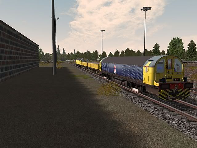 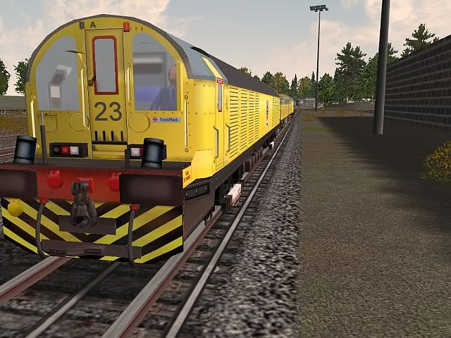 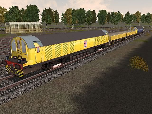 The operator is a 'familiar figure' who I believe recently noted he'd like to drive one of these in the sim Another related question - I notice a rotating beacon on the front of the cab. Under what conditions is this active? As I have 2 light switches to use in the sim, lights1 could be the front/rear lights and lights2 could be the beacon. Or is it active all the time? Thanks for any insights. Best, Jimi |
|
DrJimi
Virtual District Line construction engineer and arborist
Posts: 365
|
Post by DrJimi on Jan 10, 2007 18:52:11 GMT
Fascinating!! So the operator is effectively doing the work of the (later employed) RPA gubbins manually. Yes Darren, it looks like Off + 3 groups of 9 notches in terms of animation images needed. Or we could reduce that somewhat, as I can do position interpolation in the cab view code to make the motion look smooth. Maybe 5 for each group? Meaning 16 total frames? 5 per would actually work real nice for the physics/controller code. Looks like there's 'gaps' between the groups too. I can use the same brake code as for the 38TS so we get EP (or Windyhouse if needed). Based on TP's info I'm now much closer to realistic power/torque/accel/braking physics, using a 6-car consist (L-T-T-T-T-L) AT 280t total. That's more than twice the weight of a typical LUL 6-car SSL consist. Makes the braking "an interesting experience" EDIT: With regard to TP's question re modeling weights, etc.. Yes - the weight of each 'car' is defined, along with many other attributes like CG, aero drag, imputed inertia and momentum, rail friction, etc. A pretty comprehensive physics model. So as part of that I can define the attributes of a driving motor car (of any type) as to it's 'motor' values (power, tractive effort, and a bunch of other stuff) that let me simulate the effects of an electric motor with "LUL controls" quite well. And yes, the motor controller notches simulate defined percentages of voltage (as a result of reomoving resistances), as best we can within MSTS; although the exact effect of (say) series vs. parallel can't be exactly modeled. But I get it close. The sim takes all of that into account (effect of car weights, drag, etc.) which thus affect inertia, accel, momentum, grades, decel, braking, etc. I have good models for D78, 73TS, C69, 59TS, 38TS (which in some cases only differ in defined weights) - but this Battery Loco is a whole new beast and I'm having to 'work at the physics' to get it to behave realistically. Which I find great fun, of course As a side note, I'm fortunate to have the 2 volume set of WA Agnew's "Electric Trains" in excellent condition for a 1937 issue! Vol 1 describes the motors and control systems in great detail (including bridge transition circuitry and RPAs). I'll have to re-read and see if he also discusses these 'manual' types of controller... Best Jimi (writing the C69 Op Guide) |
|
DrJimi
Virtual District Line construction engineer and arborist
Posts: 365
|
Post by DrJimi on Jan 9, 2007 18:43:17 GMT
Excellent info sir - thank you, I will print that out for reference. Armed with that new info (motor power, etc.), I can calculate tractive effort and see how close my physics model is. If I'm figuring this right, the example 280t would be 2 x loco (60t each) + 4 x Turbots (nominal 40t each). If so, that works very nicely for a prototypical consist! Or 6 Turbots for a 360t total. I'll re-check the total train length for each and see. I now have something new to test/research this evening... Thanks much, Jimi (latent physicist) |
|
DrJimi
Virtual District Line construction engineer and arborist
Posts: 365
|
Post by DrJimi on Jan 8, 2007 23:49:03 GMT
It can be done TubePrune. I did a basic Westinghouse implementation for our 59TS and 38TS stocks. Appropriate paremeter values can be set for each 'car' as to equipment present, relevant pressures, etc. Kuju actually did quite a good job of some of the brake modeling. You can even add gauges to watch (or test in my case) what pressures are where (main res, Eq res, train pipe, etc. There's also a very comprehensive data display that a recent 'BIN' add-on has provided, such that you can also monitor (say) the end car and thus see brake lag between the cars. A few folks on here who have Westinghouse experience though my model was quite close - including the appropriate 'hisses' and other air noise FX. Fun to do - made a change from Westcode and Rheo stuff.
Best, Jimi
|
|
DrJimi
Virtual District Line construction engineer and arborist
Posts: 365
|
Post by DrJimi on Nov 24, 2006 3:19:11 GMT
I'm trying to get the physics right on our MSTS Battery Loco. I know (from tfl data) it weighs 62t. I know max speed is about 30mph. What isn't listed is stuff like Power and Tractive Effort. I have a good physics model for the SSL and Tube stocks for the consists they pull, so if I knew approximate relative power/force compared to an SSL DM I could calc it from there. So a couple of questions...
1. How many Turbots (nominal 40t loaded) does/can a single Battery pull?
2. Is that a typical consist, or are there always 2 Batteries top/tailed?
3. If so, how many can/do 2 locos pull? On what gradient?
I'm testing them exiting Lillie Bridge and right now can maintain 10mph (1 loco + 3 Turbots) up the exit bank. On the flat I can eventually hit 30mph. Braking with that load (180t) is "interesting"...
4. Do the Batteries use EP or EP+Rheo?
5. Is a 59TS control setup about right (separate brake/controller)?
Any info or pointers greatfully appreciated!
/Jimi (shunting TransPlant consists for a change)
|
|
DrJimi
Virtual District Line construction engineer and arborist
Posts: 365
|
Post by DrJimi on May 23, 2006 23:12:33 GMT
4 levels of braking (Brake 1...4) + Emergency. These use the 3...7 steps of the 7-step Westcode brake system (i.e. Brake 3 would be step 5 of 7). If these steps apply linear levels of braking (as previous comment from T/Ops in an older thread suggests), then Brake 4 should be Brake 3 * 6 / 5, Emerg = Brake 3 * 7 / 5. So Brake 4 (full service brake) should be (per my numbers) 1.27 * 6 / 5 = 1.55!?!? That feels high to me, but I stress that despite understanding the basic operation of the Westcode I'm NOT an expert. Knowing the pressure readings (at the brake cylinder) for each step would reveal all I feel. I'm also curious as to the relationship between brake pressure and actual braking force and actual decel rate (the latter two should be related simply by mass, ignoring brake fade).
Hopefully someone with far more inside knowledge than I (SB?) can comment further.
Sorry if I'm muddying the water.
/Jimi
|
|
DrJimi
Virtual District Line construction engineer and arborist
Posts: 365
|
Post by DrJimi on May 22, 2006 23:26:04 GMT
FWIW, anecdotal data re the D78 says it stops in its own length (approx 107m?) from 30mph in Brake 3. Checking my MSTS model (for which I gleaned these data) shows I used a brake force of 23Kn for a DM unit weighing 29.18t. Using force = mass * decel rate yields about 1.27m/s^2 for Brake 3. This yields a stopping time of 10.5 secs if Brake 3 were left 'on', and a more realistic 15 secs or so if the brake were 'feathered' back to Brake 1 approaching a stand.
I would also be very interested in any other data, especially for the older stocks.
|
|
DrJimi
Virtual District Line construction engineer and arborist
Posts: 365
|
Post by DrJimi on Apr 22, 2006 18:39:53 GMT
I'm fortunate that SB schooled me on the Westcode when we were building the MSTS D78 The steps are controlled by 3 wires, each going to a pilot magnet valve. Think of the operation as binary (or octal), as 1+2+4 = 7. Thus wire 1 =1, wire 2 = 2, wire 3 = 4. Thus any combination from 0 to 7 can be derived from appropriately removing voltage from each wire. Brakes off, all wires have voltage applied, thus if power fails, zero volts = brake full on. Each pilot valve allows air into the actuating cylinder, where the diameter and volume of that portion of the cylinder is different (this is where the 1:2:4 ratios happen). Progressively de-energizing the wires allows air into the 3 chambers of the cylinder, progressively raising an actuator rod that allows the air inlet valve to open further applying more air to the brake cylinders. Not knowing the relative volumes, and if the ratios are exactly 1:2:4, it's not clear to me if the steps do indeed exactly equate to "sevenths" of max brake. When we fine-tuned the MSTS D78 physics we determined that brake percentages of 30, 50, 65, 85 seemed to equate to steps 4...7 (Brake 1...4). I will leave it to the experts to decide if posting diagrams is appropriate (and correct my description if required). Note that the D78 section on TubePrune describes the electrical aspects of this also, so I don't believe this is "sensitive" information. |
|
DrJimi
Virtual District Line construction engineer and arborist
Posts: 365
|
Post by DrJimi on Apr 20, 2006 2:21:49 GMT
I'm delighted to inform you diehards we have a working Windy House brake with reaslistic DBH graphics. I put in a small graduated range for APPLY, so if you hit the increase key a few times the pressure changes quicker. LAP holds it. I also included a Max Service notch just before Emerg, so you don't accidentally dump all the air ;D
I won't tell you how many under- and over-shoots I had testing it out. Certainly a seat-of-the-pants feel needed.
We also have a graduated release EP brake version, as best as Kuju will allow.
My thanks to all who have shared their wisdom to help make this as realistic as we can. You'll see the final results shortly.
Best, Jimi
|
|
DrJimi
Virtual District Line construction engineer and arborist
Posts: 365
|
Post by DrJimi on Apr 19, 2006 13:29:10 GMT
Re the sequence light, take a look here: www.trainweb.org/districtdave/html/1938_tube_stock_7.htmlIt's the Museum '38 (one of a set of photos courtesy of DD - no idea why I didn't stumble over them before). An excellent set of color cab shots is included. Comparing Darren's work to these, I feel he done real good. In fact I'd bet he used these as a reference, if you look back to my screenshot and compare. JMHO. Thanks for the confirmation re the seq light. I'll go ahead and implement. Seems we're doing a full "make-over" of the original MSTS '38. New cab, new physics, and I'm also improving the lighting and sounds. I'm almost tempted to put an (optional) 'special' railtour blind on the front ;D |
|
DrJimi
Virtual District Line construction engineer and arborist
Posts: 365
|
Post by DrJimi on Apr 18, 2006 13:49:51 GMT
Major thanks to all of you - esp to SB for the 4:1 clue. As CSLR noted, it all falls into place with that clue. I'll implement those final numbers this evening. From other sources I also believe the blue light was "MGs on", and am told the lower one was the "sequence light". Exactly what sequence (related to motoring) I am not clear. I may simply light it when parallel is selected. Re the speedo - yes known and agreed. However, this is MSTS and if it didn't have a speedo then the unwashed masses would put up the "F5" digital HUD display -- which is even more unrealistic. We could, of course, reduce the speedo accuracy... ;D One related question -- what, if any, are the key differences between what we have here and a 59TS (cab/controls)? Not hard to guess why I'm asking... Thanks, Jimi |
|


 So don't be misled by some who seem to claim that routes can be built in no time flat. The odd few that have been, usually look like it