|
|
Post by metroland on Dec 18, 2010 18:22:02 GMT
Compromises or not, it's always satisfying to get complex trackwork with the 'right' feel to it.
|
|
Deleted
Deleted Member
Posts: 0
|
Post by Deleted on Dec 18, 2010 18:26:22 GMT
That's some very intricated pointwork there. Are the points insulfrog or electrofrog? With double slips I'd imagine the latter would be a right royal to do... switches and all that for switching frog polarity.
|
|
Deleted
Deleted Member
Posts: 0
|
Post by Deleted on Dec 18, 2010 20:53:19 GMT
That's some very intricated pointwork there. Are the points insulfrog or electrofrog? With double slips I'd imagine the latter would be a right royal to do... switches and all that for switching frog polarity. All live frog except double slips which are insulfrog I had enough with unreliable point switches and they are not easy to access! All stock on the layout has 8 wheel pick ups to minmise problems that said I do have issues with shorting on the points at times and then the DCC resets! The tube stock is a nightmare with 2 motors and chips consisting does not seem to work too well with Tenshodo Motor bogies therefore on the 1938 stock Black Beetle motor bogies have been fitted to one unit with the other one due to follow shortly. Xerces Fobe |
|
metman
Global Moderator
5056 05/12/1961-23/04/2012 RIP
Posts: 7,421
|
Post by metman on Dec 18, 2010 21:06:44 GMT
Yes, I found that a problem. All my trains have two wired tenshodo bogies in the same colour with a load of lead over them! My 5 car CO/CP train will have 2 wired back beetles. A good tactic to make code 100 look 'better' is to space out the sleepers a little. Basically the spaces look a bit close, is I'm going to leave a gap of 1.5 sleeps between each sleeper. Of course, don't make the gap too large or it looks like narrow gauge! Stolen from this nice layout... scalescenes.com/southoakroad/2007/09/track-laying-1/ |
|
Deleted
Deleted Member
Posts: 0
|
Post by Deleted on Dec 19, 2010 1:28:28 GMT
Having only just read this thread may I be permitted to make the following comments. First of all, Metroland, your track looks pretty good to me. The ramps look fine and the method reasonably simple. The finescale options are all very well but can prove expensive and time-consuming if a larger layout is being attempted. The Peco chairs look like they would have issues with fragility if used on an exhibition layout although I am sure that the 'Bay Street' layout would have shown this up by now (Bay Street is the Southern Region based layout built by the Editor of Hornby magazine, Mike Wild).
For my layout I am planning to use Peco code 100 track. I have seen many layouts that use this and it looks fine so long as the weathering is done well. It will also give clearance to use the code 60 'juice' rail. Limited clearance is always a problem when running tube stock as both Tenshodo motor bogies and Radley Models trailing bogies are very low slung. It is always worth remembering that the centre rail should only be a scale half a millimetre above the running rails. If it was level I am sure that no-one would notice!
For my ramps I will be bending the rails on the ends for most part. I may experiment with soldering wider ramp surfaces on some of the more visible parts of the LT section but this may test my sanity to the extreme! I'll also experiment with widening the sleeper spaces as mentioned by Metman. The ratio of sleepers should work out at 24 per 60' length of track.
I shall be avoiding DCC as I have so much stock that McDonalds couldn't supply enough chips! The show layout will only have six turnouts and one double-slip so I am minded to go with electrofrogs throughout. My LT stock has Tenshodos for the most part. The motorised vehicles have at least two wired together. They seem to work well enough so long as the wheels are kept clean. The exception to this is my seven car Standard stock set. This has three DMs with a single Tenshodo in each. The trailing bogies have been fitted with pick-ups to help current collection. My seven car 38TS has the two 'A' end DMs powered with a pair of Tenshodos in each.
I must also take this opportunity to thank Metroland for willingly imparting his experience on the subject. It is easy to be critical of someones efforts but we must remember that different modellers will always have thier own preferences for ways of doing things. Experience, good and bad, is there to be learned from.
|
|
|
|
Post by metroland on Dec 19, 2010 11:16:40 GMT
Metman and Glyn, thanks for your comments – I feel a longish reply coming on! To Glyn (and anyone else thinking about taking the plunge) JFDI. It’s not until you actually start handling things and trying to get your layout to ‘look’ right that you’ll really get to grips with the compromises that are acceptable to you. Eg Croxley depot has all those white rail ends which look the part in a depot area. On my track I have none. Technically some rails maybe ought to have them but if I get it wrong when some are painted and others aren’t it’ll probably look botched. So I have none. I wouldn’t say either is right or wrong but these are some choices you simply can’t make until you see your layout taking shape in front of you. (Glyn: I wouldn’t raise the centre rail. I’ve already found one problem with it as low as it is now. I have an Ivatt 2-6-2T for operating the branch shuttle (when the branch gets done – fortunately track is laid). The Bachmann Ivatt has a metal ‘lump’ underneath the centre-line which fouls my middle rail – never a problem of course with BR track. There are other types I could run but in latter years the Ivatt 2-6-2T was on Chesham branch). Ref sleeper spacing: Ugh where do I start? It’s another banana skin! The basic issues are that I didn’t know about it until long after I’d laid the BR track, but we’re also back again to compromises of having 4mm models on top of HO track. I first came across the sleeper spacing issue in an American mag, which was talking about sleeper spacing in sidings being wider than main line. From the vertical view of disused coal yard you can see I incorporated this into my disused siding and headshunt. 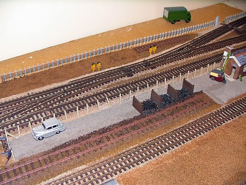 For my BR goods yard lines I did rip some lines up and try relaying a larger area with wider spacing but I was never happy so I’ve reverted to normal sleepers on Code100. What I’m trying to do is create cameos to take focus away from the detail. Eg track gang working on fresh ballast so there’s no reason for that area to be perfect  After all OO is sleight of hand in the first place so why not run with it? I’ve got a lot of time for Scalescenes as he really ‘goes for the look’. Also his kits are great in that you can do something fairly easily that looks good, and if you have the interest and determination you can put a lot more in to make them great. Can you hear a BUT coming? He’s absolutely right about the sleeper spacing, but I don’t think he’s done 4-rail? Trouble is, there’s a risk of mixing 4mm/1ft standards and OO (ie HO gauge track). When you see his properly spaced 2 rail track it looks good – only trouble is it maybe puts some newbies off having a go? WHY ISN’T THERE AN OFF THE SHELF OPTION FOR OO? (They will be saying?) (Maybe Code 75 is correct, but I guess Code 75 in itself will be off-putting as it’s ‘finescale’) Now, when you plonk Code 100 in dead centre of 4’2” track (which OO is-ish) because of the illusory nature of OO in the first place, my feeling is that it looked pretty good with the Peco sleepers. Good enough for an armchair modeller of 30 years to think I’ll run with it! As I’ve spent 30 years in the armchair, my first proper layout is clearly not top drawer, but if I compare the 4-rail lines in the pic above with recent pics of Rickmansworth and Chesham. I have to say I’m not convinced that properly spacing the sleepers to 4mm scale with sit happily with 3rd and 4th rails. My gut feel is that if you’re going to properly space the sleepers then you need to add the fiddly bits of getting scale 3rd and 4th rails, insulator pots, ramps etc. 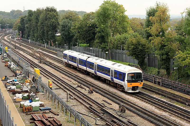 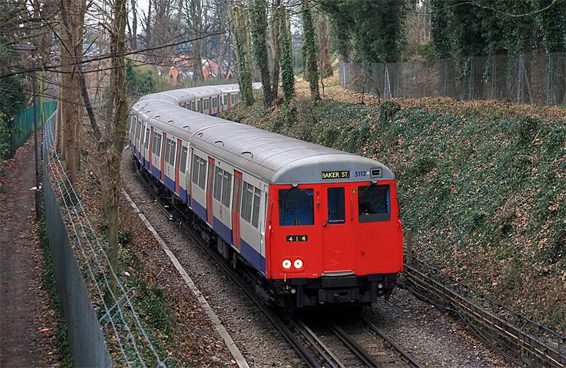 I’d love to be wrong, but given he’s talking about 2-rail track, I don’t think you can DIRECTLY apply the lesson to 4-rail, unless you make everything scale on not OO? Maybe that calculation of 24 sleepers per 60' needs some sleight of hand to make it 'look scale without actually being scale?' And finally: Glyn mentioned clearance of the outside rail. One unexpected benefit of my method was that I found it quite easy to lift the outside rail and reposition slightly. If you’ve got say every 4th or 5th sleeper with a track pin coming into the outside of the sleeper, the tops of the pins are superglued to the Code 60 rail. If you gently lift a few inches, it all comes up with one springy piece of rail with spikes already attached. Carefully press them down closer or further away and hey presto you changed the outer rail clearance without too many tears. (Sorry guys I’m not gonna lift a section and photograph it…………….) Now, do I need to repaint 2,000 sleepers a lighter colour - my brain hurts |
|
Deleted
Deleted Member
Posts: 0
|
Post by Deleted on Dec 19, 2010 12:08:01 GMT
The art of illusion is something I am well versed in! Although I am not currently bulding a layout I have been converting and building stock for the best part of thirty years. It is always easier to create the illusion of perfection than it is to create perfection! Weathering comes in handy too. I have a number of items that have been weathered over bits of dodgy lining etc.. You are correct that the sleeper spacing of 24 per 60' may need to be 'adjusted' to suit the look of OO track. I also agree with your comment re. Bachmann locos and clearance over the centre juice rail. this is why I will probably have mine at the same height as the running rail. The outer rail will need some elevation to look right. On the subject of that, did you experience any clearance problems with the pick-up shoes on EFE tube stock? They look like they hang too low down to me. I have to say that whatever you are doing, it looks good to me! I love the idea of the disused siding as this is rarely seen on any layout. Most layout builders seem to want every inch of board somehow active with train movement and they sometimes forget that the railways were about much more than that. I have also seen some modellers get uppity about detail on locos and then run them on OO track! If these people are that pedantic then run on EM or P4 or the like! There are, of course, always modellers who take it that step further. In 'Model Railway Constructor' mag many years ago there was an article about a model of a 508 EMU that not only worked off of the third rail but also had openning doors! A friend of mine used to work with a chap who built a class 74 that also worked off of the trird rail.... In 'N' gauge! It just proves the truth in the age-old tale of the Donkey. This donkey had an I.Q. of 498 but not a friend in the world. The reason? No-one likes a smart-ass!  P.S. I'd leave the sleepers..... |
|
|
|
Post by metroland on Dec 19, 2010 12:41:18 GMT
Chop the pick up shoes off EFE side bars! No-one notices from normal viewing distances, especially if the train's moving. 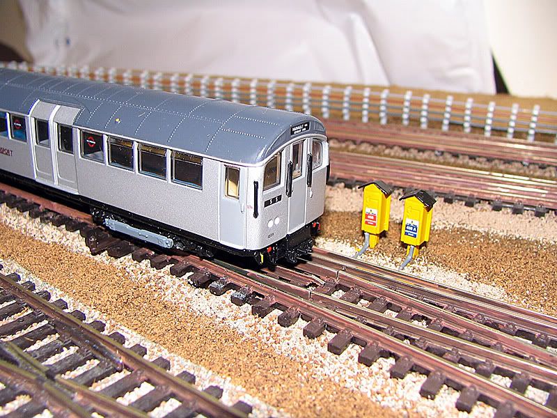 I think this view shows my outer rail is higher than running rails. Ref the distance, this is very much trial and error. My tube trains are all re-bogied with Metromodels replacements which run MUCH better. It does mean you have to cut the collector beams off EFE models and file/glue them to the outside of the replacements. A few thou can make a difference. All I can say is 'position the outer rail just a bit further outside the running line than true scale'. |
|
|
|
Post by phillw48 on Dec 19, 2010 12:47:14 GMT
On the subject of that, did you experience any clearance problems with the pick-up shoes on EFE tube stock? They look like they hang too low down to me. The EFE pick-up shoes look as if they are too far away from the the conductor rail. This is because of the too narrow gauge of British OO scale. EFE place the shoebeams in the correct position and measurements for the prototype, after all they are made as display models not intended for model railways. The problem arises with the use of track that is almost 3.5mm to narrow, if you place the conductor rail the correct distance from the running rail the shoe beam and the pick-up shoe if correctly placed will be waving about in mid air more than 1.6mm outside the conductor rail. Having said that the EFE shoe beams look far too conspicuous, and perhaps would benefit from a bit of slimming down and some weathering. |
|
Deleted
Deleted Member
Posts: 0
|
Post by Deleted on Dec 19, 2010 13:02:41 GMT
Chop the pick up shoes off EFE side bars! No-one notices from normal viewing distances, especially if the train's moving.] I did the same and also fitted Metromodels bogies and it is near on impossible to get the 4th rail to align with the shoebeams - does not unduly bother me. By pure chance I found some instructions I prepared about adding 3rd and 4th rail describing the method I used The 3rd rail is mounted on the Peco insulators however without fitting the white washer and recessed slightly into the sleepers to allow clearance when using Code 75 track I super-glued every insulated into the sleeper and onto the rail. A tip here. treat the whole exercise a bit like hanging curtain hooks. 1. Drill your holes in the sleepers first – every 4/5 sleepers as a rule but you may have make then either a sleeper spacing shorter of longer on curves, points etc. 2. Cut your rail to length. 3. Slide each insulator onto the rail carefully they are easily fall off or break so be careful. 4. Leave the insulator in the Peco sprue whole you thread the rail through makes life much easier and then cut it from the sprue 5. Lay your conductor rail with insulators next to the track and align all insulators 6. Grow a 3rd hand! 7. Fit insulators into holes and add glue hold – do several dry runs first to ensure everything is aligned before you start 8. Add a small dot of glue to where the insulator connects with the conductor rail – This adds to the strength and helps the conductor rail stand the impact of a derailment. 9. Do a few sections of track and check clearances with all the locos you intend to run on the track. The 3rd/4th conductor rail is not totally accurate however does capture is the fell of and DC electrified layout and most people would not notice and errors. Xerces Fobe |
|
neilw
now that's what I call a garden railway
Posts: 284
|
Post by neilw on Dec 19, 2010 13:08:06 GMT
re the pick-up shoes, they are the right height when hanging without a conductor rail, which is why they are a tad low when the rail itself should be supporting them. They are also slightly inboard of where they should be as the width between the shoebeams is slightly undersize. If you use the metromodels bogie with the EFE sideframes grafted on this can be put right, although as said, the average viewer would be hard-pushed to see the shoes at all!
|
|
Deleted
Deleted Member
Posts: 0
|
Post by Deleted on Dec 19, 2010 13:26:22 GMT
The picture below shows my Radley Models L11 Acton Works Shunter (body not sitting quite right as it was a test run) and this shows a much better alignment of the shoebeam and the 3rd rail. The centre 4th rail one is spot on too! ;D 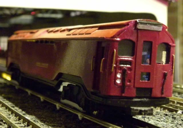 Xerces Fobe |
|
|
|
Post by metroland on Dec 20, 2010 15:27:00 GMT
I'd completely forgotten that the issues of clearance with the outer rail weren't just about the grey beam but also the replacement Metromodels bogies. It's tricky getting close enough to get the detail and keep focus but hopefully this is what I mean: 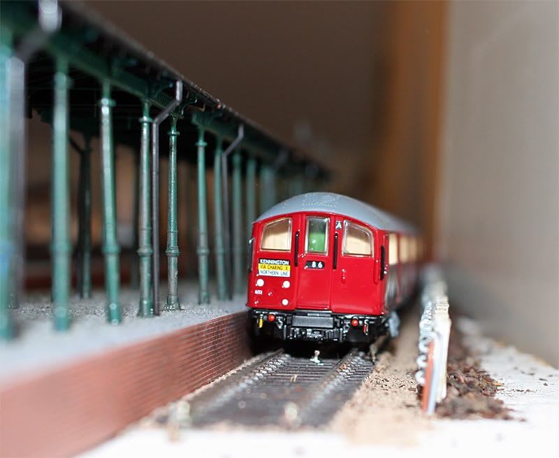 You will see that the grey beam which has been cut and re-glued is actually wide of the 4th rail but the edge of the 'square' replacement bogie underneath is very close to rubbing the outer rail. I hope you all won't mind me repeating a pic from other thread but to give an almost side-by-side comparison, here is 'normal viewing distance' where the incorrect position of grey beam doesn't show: 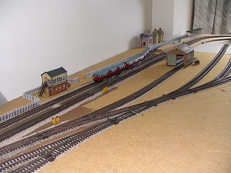 |
|
metman
Global Moderator
5056 05/12/1961-23/04/2012 RIP
Posts: 7,421
|
Post by metman on Dec 20, 2010 23:26:23 GMT
I wouldn't loose sleep over it either. After all we all have crazy moments where we think, maybe I can set up door fault lights on the trains when in platforms!! Life's too short ;D
|
|
|
|
Post by railtechnician on Dec 21, 2010 4:05:04 GMT
I think the white ends are great and a good way of doing rails in depot areas, and areas where there's plenty of foot traffic (eg to the canteen beside the station). I avoided them on 'normal passenger running lines' (for want of a better description) as I wasn't so sure it would look as appropriate. BTW seeing your lineside cabinets reminded me of something that's been niggling me. When I look at the real thing today, or pics of the past, I can't seem to see any rhyme or reason as to how many cabinets to put in or where. There are obviously more of them by signals, or signal cabins, but I can fathom just what is going to look 'right' for the lines I'm building. Any clues? Anyone? Mmm, cabinets ? First of all a little terminology, the site of signalling equipment (the relays, capacitors and transformers) is known as a signal location (even if there is not a signal there!), the cabinets are actually called Kiosks and Cases. A case may be a transformer (T) case, a condenser (capacitor or TH) case or a relay (TR, GR, PGR etc) case. A typical LT standard signal location would have one transformer case two condenser cases and two track relay cases because a transformer feeds two adjacent track circuits. If there is also a signal at the location then then will also be a signal relay case, alternatively a repeating signal location may simply be a single PGR relay case or possibly a PGR case with an adjacent transformer case. In a standard location the transformer case is usually the centre case of five cases and above it a 600v link box which is connected to the local signal main 600vac supply. The condenser cases may be one either side with the track relay cases at each end or an alternative arrangement (there are standards but it really depends upon who did the original installation and the arrangement does vary from line to line and site to site). Where there are points and other circuits the relays are generally within the local interlocking machine room (IMR) or signal cabin relay room in open sections. Modern Kiosks, mounted on concrete plinths, are generally a complete replacement for a signal location containing the 600v signal main connection links, the 600/100v transformer, the track condensers and the track relays etc. Where there is a signal or repeating signal at such a location it can be mounted immediately atop the kiosk and the kiosk will also. contain the GR or PGR relay. Older type kiosks mounted on a concrete base usually contain the condensers and relays for two track circuits or several miscellaneous or other relays. It is difficult to be specific about what is contained at each location so it is not straightforward to illustrate the rhyme or reason for positioning of signal equipment but I'll do my best. Think signalling! Start with auto as all it needs are TRs and GRs. A signal has a limit of control or 'selection' and that selection is all the track circuits from and including its replacement track up to and including the replacing track of the signal ahead. The selection may contain anything from three or more track circuits so if there are say four track circuits in the selection then four TRs are required and a 'location' normally sits close to the boundary of two adjacent 'tracks', the location will be the standard five case layout if it is somewhere between signals but if it is at a signal position then it may be a six case layout TR,TH,T,TH,TR,GR or alternatively it may be a single 'track' four case location, say TH,T,TR,GR. Similarly where there is a repeating signal it may simply be a single location case with a PGR or it might be a four case location, PGR, TH,T, TR if the track relay is also mounted at the same point. As a rough rule of thumb the above is quite authentic for say North Ealing to South Harrow on the Picc. Taking South Ealing to Northfields and beyond the signal equipment is generally in kiosks so on average one kiosk every two 'tracks' per road would be expected and that is pretty much the case. With four tracking, kiosks for two adjacent roads are often found in the same 'location' side by side and sometimes a third kiosk will contain additional circuitry e.g timing section relays and inductor circuit amplifiers etc on the approach to a controlled area. In controlled areas (basically where there are converging and diverging routes, sidings etc) most of the relays are housed in rooms as mentioned previously but there will still be some track relays outside and some signal relays too although modern practice is to have as little equipment at trackside as possible. However, where there are long distances between stations it is not really possible to avoid trackside locations, e.g. on the Met. There are thus judgements to be made according to the line and the time that is being depicted although one must not forget that there are exceptions to every rule and and we used to say on signals, "If one exists then it is a standard!". Down the tube it is much the same but generally a location will contain two track circuits the signal and any ancillary equipment arranged in familiar layout on the tunnel wall. Other equipment is mounted in end of platform tube relay rooms and IMRs reducing what has to be mounted in the rather inaccessible tunnel locations. Another thing to consider where you have points is the old 'hot oil' point heater consoles which were generally one console per end of points usually mounted very near to each end and sometimes in clusters of twos and threes. Modern point heater cubicles are basically transformer cubicles feeding strip heaters clipped to the switch rails and mounted further away than the old consoles were, each serving multiple ends of points. Another point to note is that signal cases and kiosks are painted silver and telephone cases and kiosks are painted green. Telephone kit is also seen trackside using identical kiosks but housing cable main distribution frames (MDFs), pulse code modulation repeaters (cylindrical grey housings bolted on the outside), there are also "cow's udder" telephone cable link boxes and station to station headwall phones in green relay type cases at platform headwalls (not nowadays as they were replaced by green or grey weatherproof phones in the 1980s). There were also such things as channel change beacons for the old train radio system which had equipment in grey painted standard Westinghouse relay cases. Hopefully the above will go some way towards helping you populate your layout. |
|
|
|
Post by phillw48 on Dec 21, 2010 9:31:22 GMT
Thanks for that Railtechnician. Perhaps someone can find some photographs of the cabinets (sorry kiosks) that would be a great help.
|
|
neilw
now that's what I call a garden railway
Posts: 284
|
Post by neilw on Dec 21, 2010 10:07:27 GMT
many thanks Railtechnician, very useful info for we modellers. On the subject of shoe positioning, here is a photo of my prototype conversion grafting the EFE sideframes onto the Metromodels bogie. 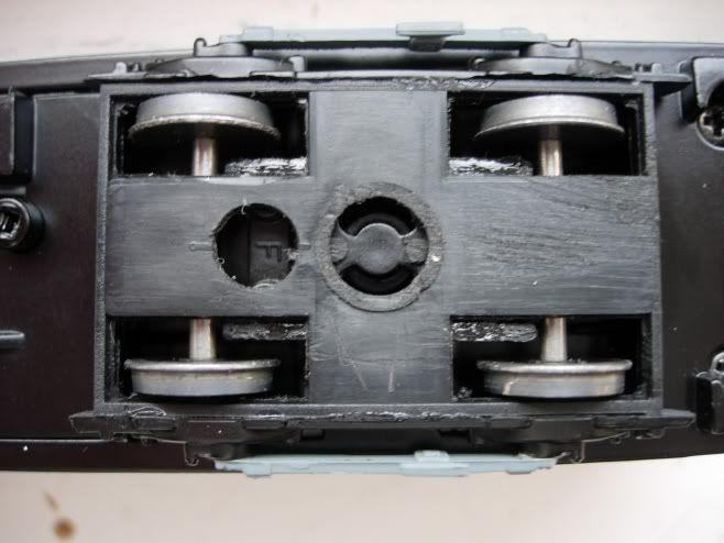 The trick is to thin the sides down to the point where the outside of the shoebeams line up with the outside of the solebar, as they do on the real thing  As I model in EM, this puts the shoes in the right place relative to the conductor rail. I showed my prototype to John Polley when he visited me last year, and it was from here that he developed his "product", albeit slightly different to mine-I use the bogie upside down to give more clearance above the centre conductor rail, etc |
|
|
|
Post by metroland on Dec 21, 2010 13:15:16 GMT
Railtechnician: Thank you SO much for your detailed reply - I had no idea where to start with this as it just seemed such a black art.
Not sure just how long it will take me to absorb and apply to my layout but I've no excuse now for not knowing what I SHOULD be doing.
Another question on a related issue if I may:
Ref the lineside cable runs of the 50's era - am I correct in thinking that at the time they would have been newly installed, the top cable wasn't a cable at all but a metal conduit?
(On my layout I've used brass rod sprayed with grey primer to represent this, with 'cables' on the lower 3 runs).
|
|
mrfs42
71E25683904T 172E6538094T
Big Hair Day
Posts: 5,922
|
Post by mrfs42 on Dec 21, 2010 13:25:18 GMT
cable wasn't a cable at all but a metal conduit? Not quite - it's the compressed air main. |
|
|
|
Post by metroland on Dec 21, 2010 13:34:04 GMT
cable wasn't a cable at all but a metal conduit? Not quite - it's the compressed air main. Thanks but am I right in thinking it has smaller cross-section and is made of different material from the other cables? (Am total novice at this kind of technicality). |
|
|
|
Post by metroland on Dec 21, 2010 13:42:25 GMT
Neilw: Thanks for the pics - I guess we have quite similar solutions. I could never get the grey beams to line up with the side of the cars and my 1938 stock will probably need attention next winter to narrow them down at bogie height. After about 10 cars I got a bit better and although my 1962 stock still doesn't line up precisely with the edge of the car, it is getting there I think. 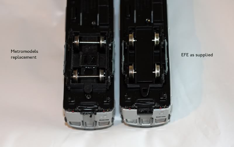 |
|
mrfs42
71E25683904T 172E6538094T
Big Hair Day
Posts: 5,922
|
Post by mrfs42 on Dec 21, 2010 13:44:43 GMT
No, larger cross-section (it is a hollow tube) and made entirely out of metal.
|
|
Deleted
Deleted Member
Posts: 0
|
Post by Deleted on Dec 21, 2010 14:09:13 GMT
The air main carries compressed air for things like trainstops and proper points (air-operated ones). Hence is like M said, metal hollow tube. You'll see stop valves at various points along it for isolating a leak.
|
|
neilw
now that's what I call a garden railway
Posts: 284
|
Post by neilw on Dec 21, 2010 14:12:13 GMT
metroland, your conversions are looking good! It is lucky that the EFE models are slightly too narrow at that point as it helps with the mod (it was also handy that I could pop into the garden for a measure-up of the real thing, not today though, absolutely freezing here!)
Regarding cable runs, there is a very detailed thread from a few months ago with some excellent (as always) info from our freind Railtechnician which explains everything you need to know about pipes and cables. It's headed "cable run info sought please". I am still experimenting with the Radley Models hangers but am still not 100% happy and need to find some way of making the intermediate ones which just hang off the air main.
|
|
|
|
Post by metroland on Dec 21, 2010 14:19:20 GMT
I thought long and hard about the Radley hangers which seem a bit large. However there's so much to do and so many compromises to make (for those of us who can't face EM  ) that I decided to go with them. Am hoping that in time, when I come back to them I'll be able to weather them in a way which makes them fade into the background a bit more. |
|
metman
Global Moderator
5056 05/12/1961-23/04/2012 RIP
Posts: 7,421
|
Post by metman on Dec 21, 2010 17:51:58 GMT
I'm not the biggest fan of the Radley Models cable hangers either. I may be able to do something about it though.....
They do appear a little chunky. Its really because they appear too deep. If some of the back could be shaved down a bit and they will still be able to be cast, then he may re do them for me.
In the meantime we're releasing the 1913-21 Circle Stock (the trailer arrived today for me to inspect) and then CO/CP upgrade kits. Lots to do.
btw, looking good guys....
|
|
|
|
Post by railtechnician on Dec 21, 2010 20:19:08 GMT
Not quite - it's the compressed air main. Thanks but am I right in thinking it has smaller cross-section and is made of different material from the other cables? (Am total novice at this kind of technicality). If you look further back in the topics (not too long ago) you will find a detailed account that I gave of what is to be found in the cable runs. I explained cables, their numbers, sizes, usage etc and their standard positioning when someone asked about the bracket runs. Specifically the air main in the top shelf of the 4 way signal bracket run is 1.5 ID galvanised pipe (about 2" OD) red lead undercoated and then finished in silver paint. Note that the air main is only in the top shelf in open sections, in tunnel sections it is in the bottom shelf ! Edited to suggest: Try looking back through the images in the quiz section for photos showing signal locations etc , also check the flickr webpages too. When I get a minute I'll see if I can find any and point them out but I'm a little busy playing with other things at present. |
|
|
|
Post by metroland on Dec 21, 2010 21:05:12 GMT
Railtechnician: Thanks for that - I've now found the earlier thread about cables etc. I won't be doing underground sections any time soon  |
|
|
|
Post by metroland on Feb 16, 2012 13:27:34 GMT
I’ve been sidetracked a bit this winter by building a little demo stand ‘How To Cheat At 4 -Rail’ (with apologies to Delia). An exhibition is being arranged by Xerces Fobe 2 of this board 19May2012 near Maidenhead: www.rmweb.co.uk/community/index.php?/topic/46957-thames-valley-model-rail-expo-2012-19th-may-2012-knowl-hill-near-maidenhead-berkshire/page__hl__%2Bthames+%2Bvalley__fromsearch__1The display is a fairly straightforward setup with Peco 100 at the bottom, untouched. 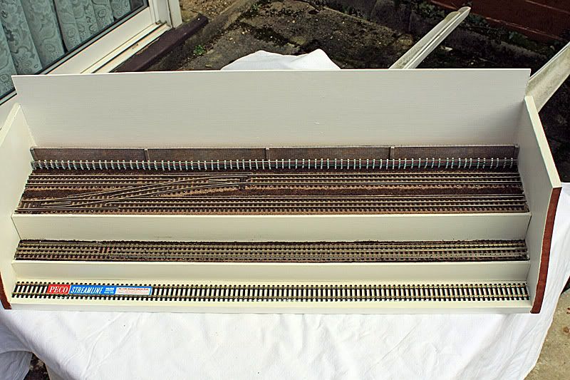 The middle level has the track ballasted and the rails left un-weathered, but with track pins showing how I hold the bits in place whilst glue is setting. (They’re a bit dark in the pictures - not sure if I’ll try and find coloured pins for display or keep with the track pins. These are after all what I’ve used, and I’m trying to show people how you can follow the KISS principle and get something with ’the look’) The top level has 2 tracks with a crossover, ballasted and weathered, but should be within the capabilities of anyone. All track parts are either cut, glued, pinned, filed or bent. No soldering, and it’s all in OO. In anyone’s motivated to have a go with soldering, or EM or P4 etc etc then so much the better, but this is all about low-tech. 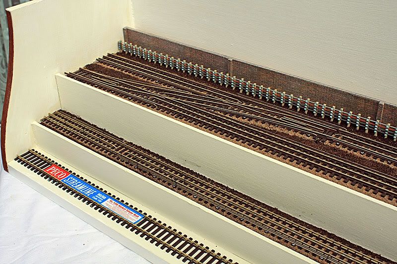 On the day I hope to have some relevant stock on the RH end of each track. If you are attending please drop by. |
|
Deleted
Deleted Member
Posts: 0
|
Post by Deleted on Feb 16, 2012 14:08:00 GMT
I have also booked 2 layouts with an Underground theme for this show Hopefully I look forward to seeing some District Dave Forum members at this show 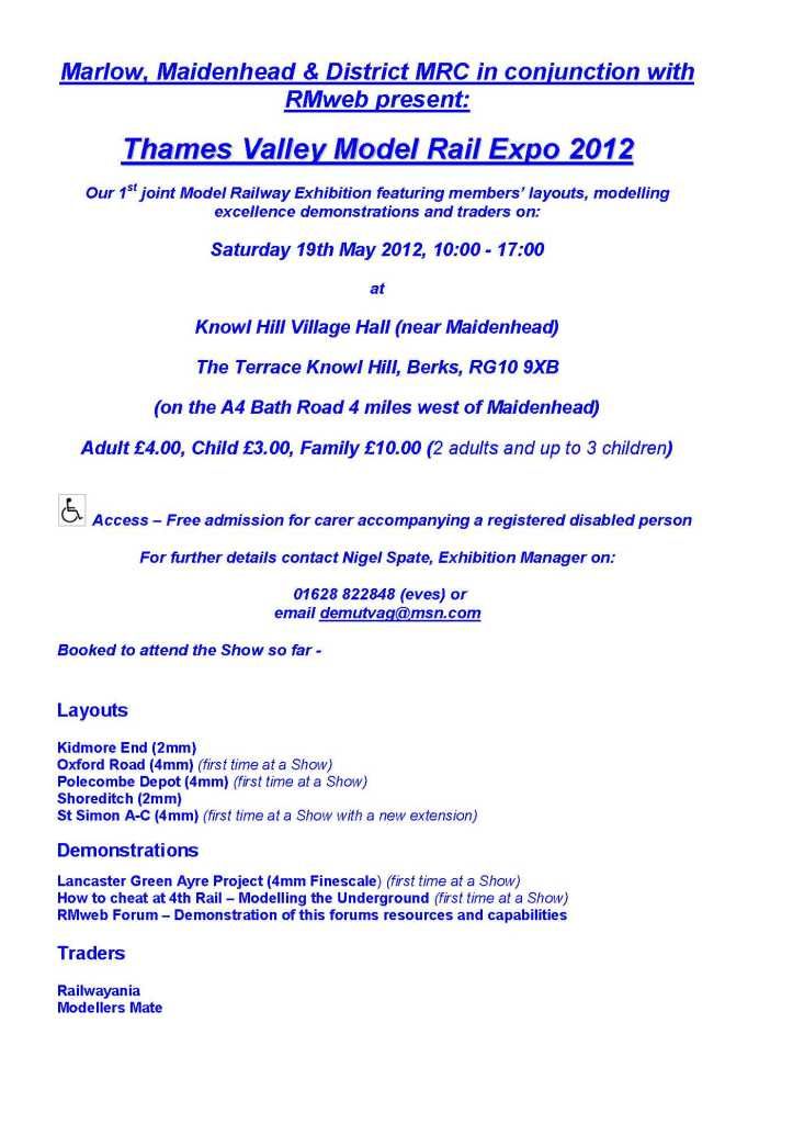 XF |
|


