Deleted
Deleted Member
Posts: 0
|
Post by Deleted on May 11, 2015 13:13:46 GMT
I have returned, and sadly it's taken me a while to get round to starting another project, as not everything I model is London Underground / Transport, but now most of my Southern models are done I can now do things that I wanted to do some time ago, and brought various parts / Chassis to do them but never got round to it. I will start posting soon, here's a little introduction: Metropolitan E-Class, Scratch build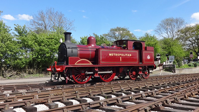 Now that most of my Bluebell models have been completed, I have turned my attention to locos that I would like either through seeing them on rail tours, or when I was a little younger at preserved railways. As some of you will know I have 3D printed a set of Metropolitan coaches, the ones that have been run around London over the last couple of years, the 2 main steam locos which were involved was a small prairie L150, and the Metropolitan Railway E-Class from the Buckinghamshire Railway Centre, or better known as Met 1. There is one kit available a SE Finecast kit…. But you know me, I like to make things difficult for myself, so I decided to scratch build it instead, where’s the fun in building a kit? I have had this model and loco in mind for a while, I purchased a rather broken Hornby M7 chassis, missing most of it’s bits, no brake hangers, no bogie, basically just 2 driving wheels a metal block and a motor, would be a shame not to use it. So research began earlier in the year by finding an original engineering drawing for the Metropolitan E-Class on Flickr thanks toe the London Transport museums Flickr feed, this was a good find and gave me a good base to work from and a few just about readable measurements.  With basic measurements length, height, widths ect… this meant I could now start planning out the model and would it work with a Hornby M7 chassis. Usually what I would do at this point is overlay a side profile image of an M7 over the top of the plan above to check it all fits, now with free 3D modelling software tools like Google sketchup it’s quite easy to draw a chassis, and then generally draw an outline of the body. 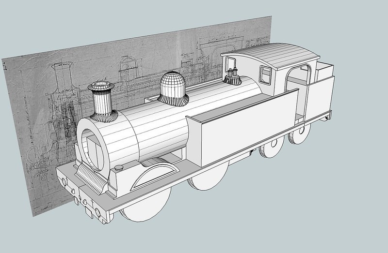 After seeing that it was possible to do the model then I drew up a plan what I needed, I intend to use only 3D printing for smaller parts of this model, the rest will be scratch built. The chassis will be a Hornby M7 chassis, which I purchased from a well known auction site, it was quite badly damaged so got it nice and cheap (£20) 3 years ago. Most of the structure will be made up from Plasticard, mainly 2mm thick for the running plate, 1mm for the tanks / bunker, and this will be reinforced if you like with sheet metal, Brass or nickel. The main boiler barrel will be 20mm diameter so either plastic tube or brass tube will be used with a wall thickness of 1mm. Some parts will be castings, which adds weight, I was lucky to already build a SEF kit of one of these so have various part numbers / names for castings, so I will be able to order them as spares. I shall post some more info in the coming weeks, as I was hoping to find a Metropolitan A-Class also. |
|
metman
Global Moderator
5056 05/12/1961-23/04/2012 RIP
Posts: 7,421
|
Post by metman on May 11, 2015 19:14:29 GMT
Looking forward to this. I bought the kit if an E class but have no chassis. Bought an old M7 but this was knackered!!
|
|
Deleted
Deleted Member
Posts: 0
|
Post by Deleted on May 11, 2015 22:33:54 GMT
I did consider buying the kit, I am guessing it's the SE Finecast / Wills version? Only one I know of, off the top of my head. Do fancy having a go at an A-Class if I don't find a kit I guess I will have to do that from scratch to.
I shall post something soon, at the moment it's looking quite good.
|
|
|
|
Post by northfields on May 12, 2015 7:12:04 GMT
I think someone on has already modeled the A class on shapeways based on the keyser kit with some refinements. If you search for metropolitan in shapeways you should find it though I imagine some fettling and improvements could be made.
|
|
Deleted
Deleted Member
Posts: 0
|
Post by Deleted on May 12, 2015 12:59:45 GMT
Yes indeed... I have seen them and someone at my club has one but I wasn't that impressed with a number if areas on the model, so ruled it out of my choices.
So it was either Keyser or idk / ibk kits can't remember off the top my head.... Could always scratch build one lol, depends if I can get a drawing or not.
|
|
|
|
Post by arun on May 12, 2015 14:31:27 GMT
If you want accurate drawings [suitable for modelling] of the 4-4-0 "A" tank, then look no further than "The Anatomy of the Metropolitan Railway 4-4-0 Tank Locomotive" by Peter Manning. This was published in 2013 and contains uncluttered drawings [of the complete engine as well as individual components] allowing you to make an accurate model in pretty much any scale you want. It is available from:
Mr JW Lloyd
18 primrose Avenue
Hyde
Cheshire SK14-5BU
0161-368-4740
HTH
Arun
|
|
Deleted
Deleted Member
Posts: 0
|
Post by Deleted on May 12, 2015 21:47:59 GMT
Thank's Arun I will look in to that tomorrow. Many thanks
|
|
Deleted
Deleted Member
Posts: 0
|
Post by Deleted on May 14, 2015 16:52:00 GMT
Sadly looks like the book is out of print and no longer available. Hopefully a kit will come up when I have finished this one who knows.
|
|
Deleted
Deleted Member
Posts: 0
|
Post by Deleted on May 22, 2015 11:21:35 GMT
Right first post of this build, even though it's pretty much complete from my point of view.
Firstly, I used some 2mm (80/000) plasticard for the base of the running plate, this would be reinforced with nickel silver plate (0.3mm) which will be glued on to the plasticard with Araldite with a 0.3mm overhang on either side as the running plate usually would. At this point in time I couldn't find a sheet big enough to do the whole of the running plate, but later found some sheet metal big enough to do the job, hence why it's made from 2 parts.
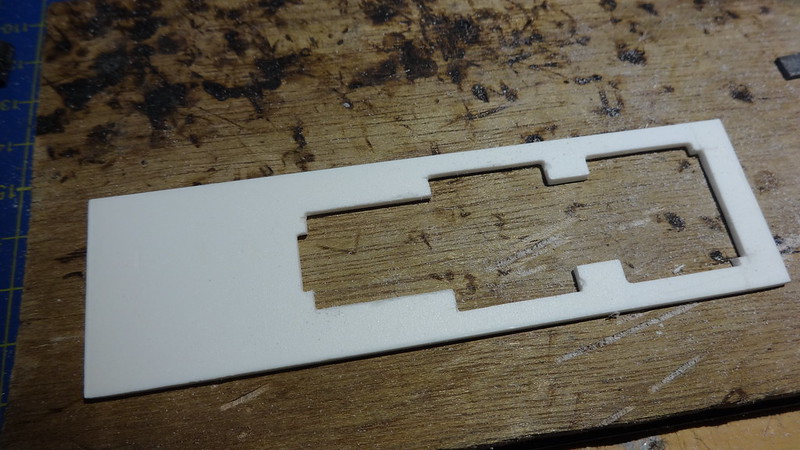 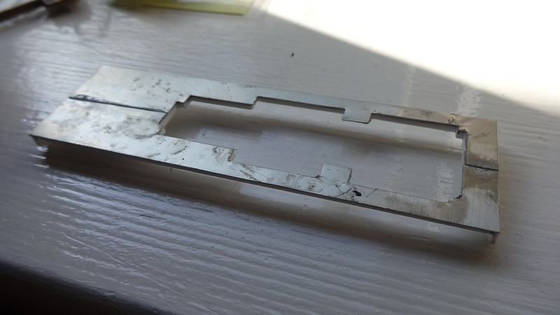
I went ahead and 3D printed the smoke-box from the 3D model I created to get the idea of how it all fits together, I have designed a grove in the rear of the smoke-box to take the brass tube, so it will slot in to the rear, and be glued in place, the underside of the box is to allow the M7 Hornby chassis to fit. The brass tube measures up 20.0mm Diameter x 19.0mm inside diameter x 250mm long.
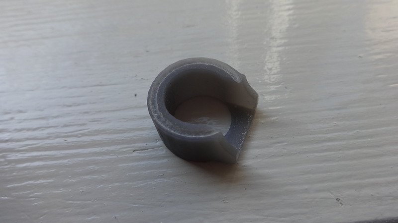 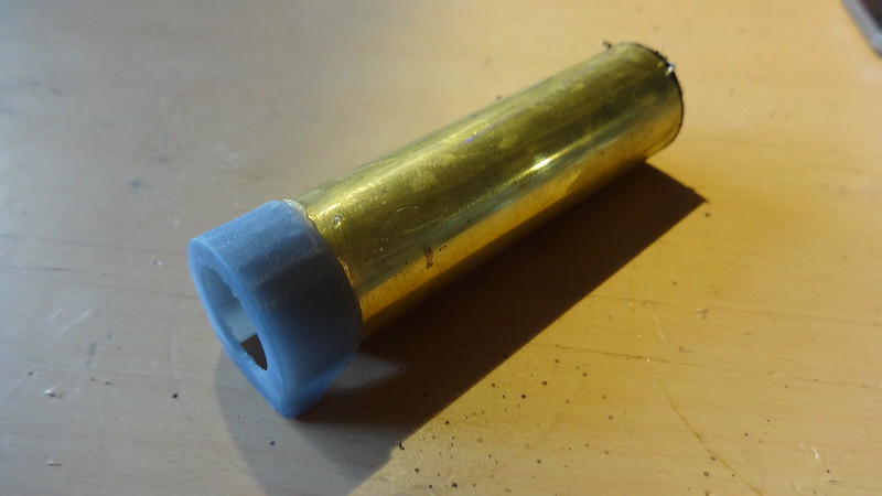
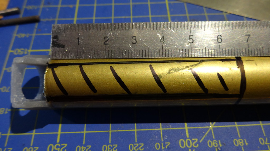
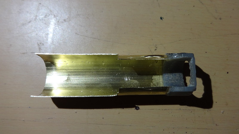
You will need to open up a slot in the underside of the tube, same as the smoke-box end, and then pretty much cut the tube in half around the tanks to allow the motor and electrics to fit. The area behind the splashers also needed opening up so they were not touching the wheels.
That's all for now, will go on to building of the body ect..
|
|
|
|
Post by philthetube on May 23, 2015 18:45:09 GMT
|
|
Deleted
Deleted Member
Posts: 0
|
Post by Deleted on May 23, 2015 20:35:22 GMT
Thanks for the link but no problem I managed to get a copy of some plans as the 4-4-0 was built prior to the Met A class with some changes, it's actually worked out ok and saved me a lot of money by the looks of it, as I won't pay any more than £15 - 20 for a book.
|
|
Deleted
Deleted Member
Posts: 0
|
Post by Deleted on Jun 1, 2015 12:54:26 GMT
A bit of info on the Chassis, the chassis I have had for a number of years, which I picked up from eBay I tend to pick up cheap things that look un-repairable but I usually find a use for it some where. Anyway I brought this Hornby M7 chassis Long framed version for about £20 or so, and now it has a new future not as an M7 the wheel size is slightly bigger by 1 inch at 5ft 7 (22.3mm) than the Metropolitan E-Class 5ft 6 (22mm) Not that we are going to notice the missing 0.3mm... the main thing which picking a chassis is more the spacing and yes getting close to the wheel size as possible. Sadly the bogie that came with the chassis would of been too long anyway so that's gone back in to the spares box. Overall the chassis needed a few repairs, new brake block set (x9586) and a new keeper plate on the underside (x9581) cost about £10 to get it running again, so the chassis was stripped down, painted as were the wheels, approximately 5mm was removed off the front, and also the chassis was cut at the rear jest behind the motor bracket. 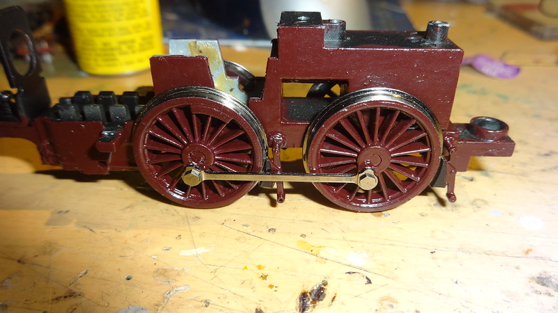 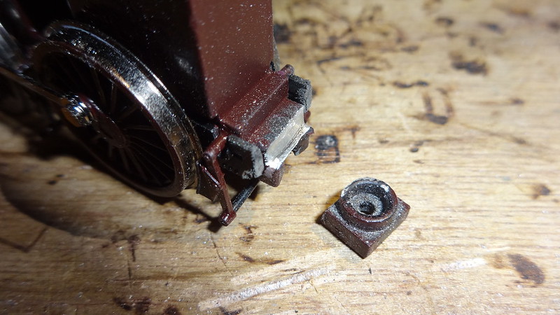  |
|
Deleted
Deleted Member
Posts: 0
|
Post by Deleted on Jun 1, 2015 13:40:53 GMT
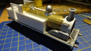
Next on to the body construction, before proceeding I checked the running plate on the new cut down chassis to make sure it fits, most if not all of the body will be made with plasticard mainly 1mm thick (40/000) using the measurements from the 3D model, Sides and fronts of the tanks as well as the bunker sides and back were cut out then fixed together using some superglue.
The castings were purchased as spare items from SE Finecast, and are seen loosely fitted to the model. Purchased were: Chimney, Done, Door, Safety Valves, back-head, and tank filler caps.
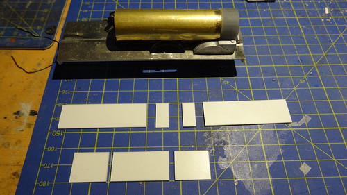 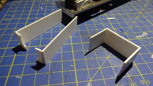 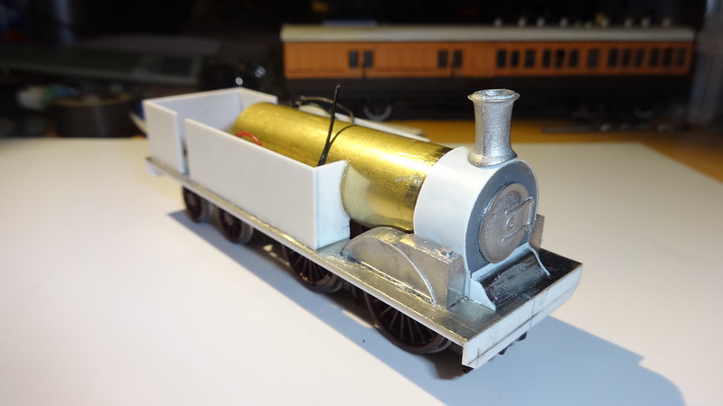
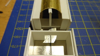
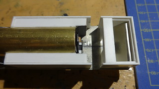
With the main structure now built I can now progress with some internals of the bunker, and mounting for the brass tube at the back head end, again all using 1mm plasticard. Also made is a prop to keep the tube level so a structure can be built up around it. You can also see the bunker taking shape with the slope down to the floor made from off cuts of nickel silver sheet, to keep the weight down on the rear. The bunker was designed as a double wall with the internal wall being 2mm shorter in height for mounting of the shelf at the back of the cab, and also for the bunker extension plates which we will see later.
|
|
|
|
Post by metroland on Jun 1, 2015 15:47:40 GMT
Nice progress bluebell87 - what colour did you use to replicate the red/maroon on the chassis?
|
|
Deleted
Deleted Member
Posts: 0
|
Post by Deleted on Jun 1, 2015 21:59:11 GMT
Hello Metroland, it's a good question, I picked up some LT maroon from Phoenix paints in March with this in mind, but it was way too dark, so I assume that was for an earlier livery like it was running before the last overhaul with the chrome dome, luckily I had LT Rail red which is from their Cherry paints range, but again that was way too bright, so only way was to modify it a bit. After seeing Met 1 after it had it's wheels done, the red did seem very red I took some my paints a long to compare, and the colour was in the middle really of the 2, so I gradually made it darker till it matched what I saw, as the light can be also confusing I have seen images where it looks a very dark maroon, and others like the image at the top of the page where it's quite red. So c163 LT Rail red I used then made it a bit darker is the best way I can describe it..
|
|
Deleted
Deleted Member
Posts: 0
|
Post by Deleted on Jun 3, 2015 0:04:28 GMT
I turned my attention to the bogie at the rear, needing a bogie I rummaged through my spares box and found a spare bogie from one of my Will’s O2 tanks, which have the same axle spacing’s for the bogie of 20mm, with trouble finding 15mm wheels for the bogie (3ft,9) I had to settle for 3ft8 which is about 14.6mm. The wheels came from Mainly trains, and made by Gibson. 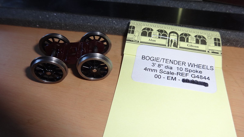 Next issue was to relocate the bogie mounting point, I decided to do something similar to the M7 chassis I had just removed. Using off cuts of the nickel silver sheet, I constructed a bogie mount, this was attached to the underside of the body the plasticard was cut away allowing room for the wheels and also to allow the newly made bogie mount to be soldered on the underside of the running plate. A hole had to be cut in the topside to allow a screw for adjustments and removal. Holes were also made for electrical wires to pass through to the motor to allow for bogie pickups to be fitted at a later stage.   Back to the chassis... on the chassis, quite a bit of work was needed on the running gear, brakes ect… I used some etched Brake rigging set from Mainly trains (MT186- (Mainly Trains) Loco Brake Rigging & Accessories) but also because the Met tank has different mounting points under the firebox some new mounting points had to be made. 2 addition mounts were created at the rear for the brake rigging to join, this again using off cuts of the metal sheet as above, you can also see I have also replaced a missing sand box just be hind the read driving axle. I made a 3mm hole in the bottom of the running plate for the cylinder to apply the brakes, a 0.5mm hole was made to allow the wire enter the cylinder. 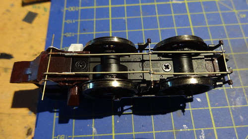 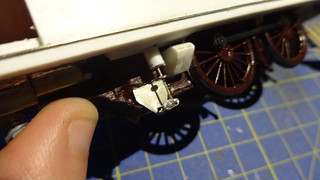  That's all for now, more towards the end of the week. |
|
Deleted
Deleted Member
Posts: 0
|
Post by Deleted on Jun 3, 2015 22:23:26 GMT
Now the chassis is just about sorted till the point of electrics and connections to pickups on the bogie attention goes back on to the body. Time for some drilling of holes for parts.
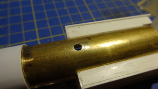
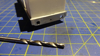
First in the boiler barrel for the dome, 4mm hole and the dome is glue or if you prefer soldered in to place. The safety valves and chimney can be glued on, although at this point in time I still had no real idea of how to attach the body to the chassis which I resolved a bit later on.
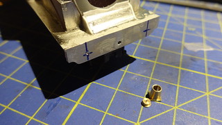
For the sprung buffers I shall be using the closest I could find, which were mainly the GWR Collett type buffers which have a slight taper to them.
To fit these you must drill a 3mm hole in the buffer beam, and also solder the ends in to the buffer housing, believe these are made by Gibson
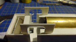
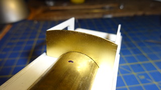
Time was right to start building the cab, I planned out the cab, by images, and plans, using these I managed to create the shape of the cab opening and window openings. The more difficult job was to establish where all the holes were in the front of the cab, for various pipes ect… but I managed to do this using some photos found on Flickr from the previous runs of Steam on the Met.
The sides were made from 1mm plasticard, with some plastic strip to go around the cab opening giving it a slight lip around the edge. The front and rear of the cab I made from the brass sheet purchased from an excellent model shop on the Isle of Wight (UpstairsDownstairs), as I wanted it to be as thin as possible so it didn’t look like the glazing was a mile behind the front face of the cab.
I used tin snips, a small barrel sander, and various drill sizes to make the opening for the windows and pipe work, and using needle files to open up the window opening. The front of the cab was soldered on to the boiler barrel to add to the strength of this area.
 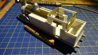
|
|
Deleted
Deleted Member
Posts: 0
|
Post by Deleted on Jun 5, 2015 13:39:09 GMT
Now we are in to working with brass there will be a few more parts to be made, the top of the bunker rails / sides are to be made of one strip of brass, about 7mm wide and then bent in to shape, the brass strip was glued to the plasticard, and also soldered to the rear of the cab.
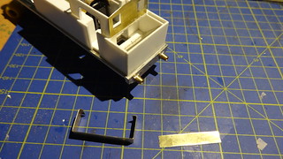 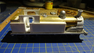
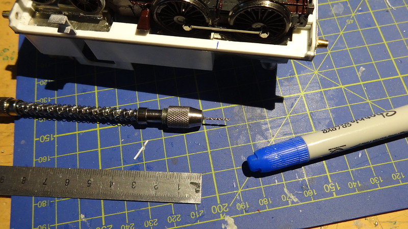
Adding a bit more detail the steps were added to the underside of the running plate, although I would probably recommend adding these towards the end of the build, The steps are castings which I acquired from SE Finecast. A small 2mm hole is drilled for the locator on the back of the step to go in to, these can be glued with Superglue Gel or Araldite.
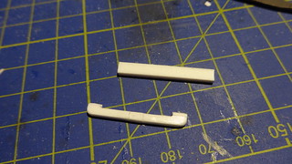
Whilst on the area of the steps, behind the cab steps there is a pipe / water channel that connects the main water tanks and an additional tank which is under the coal bunker. I made this with plasticard again 2mm thick, I made a small groove in the top edge for them to be glued on to the plasticard underside of the running plate.
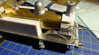
This is an area which I believe is probably the most difficult part, the hand rails are quite unique on Metropolitan 1, being held on the smokebox by a normal handrail holder but the other end of the hand rail going through an opening on the top front edge of the tank, getting this wrong means it won’t line up and it won’t be straight and it will look well rubbish.
I did as much simulation work on the 3D model to ensure measurements were correct. My original idea was to cover the front and sides of the tank in Brass and then add rivets on to them by a centre punch, but I changed my mind after doing a test piece and the rivet head size was to big.
So I decided to use the 0.10mm brass for the tank fronts only, I added the handrail knobs or holders to the sides of the smokebox and ran the handrail wire through to mark the point on the front of the tank where the hole should be.
The brass sheet was cut with tin snips, and a small barrel sander to get the curve of the tube/boiler in to the side of it, a small hole was drilled for the handrail wire, and the surrounding material was filed away.
 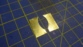
Before adding these to the front of the tanks, I added just a bit more detail, there is a small step around the middle of the front of the tank, again I made use of some off cuts of brass, cut it in to a 2mm wide strip, bent it in to shape, cut off the excess, filed down the sides of the step so they angle in to the brass front. And these were soldered in position. After this fronts were attached with Araldite to the plasticard before the glue set I check the alignment to the handrail holder on the side of the smoke-box.
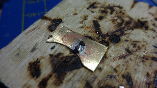 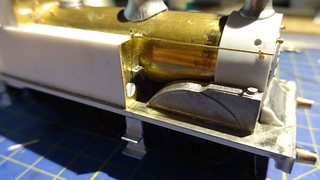
|
|
Deleted
Deleted Member
Posts: 0
|
Post by Deleted on Jun 10, 2015 21:19:24 GMT
Next step of detailing was adding hand rails around the cab opening, and also on the end of the tanks. I was originally going to use brass strip but couldn’t get hold of the right size, but could with plasticard strip, so cutting to size and and then drilling with a small hand drill with a 0.45mm bit for the wire.
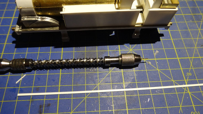
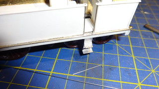 
Continuing on the detail theme, the buffer beams, I have used a few of these methods on other builds , for lamp irons I used split pins 1/32 Inch x ½ Inch which were bent in to shape and soldered in on the front buffer beam for the middle iron, and the running plate for the outside irons. A small hole was drilled in to the top of the smoke-box for the top lamp iron this was glued in to place. The vacuum pipe from Romford this was soldered to the buffer beam, this was also fitted to the rear. The lamp irons on the rear of the bunker were fitted in a similar way to the smoke-box one, a small hole drilled a small amount of super glue gel and then trimmed.
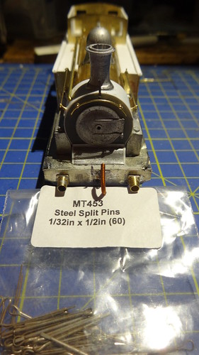 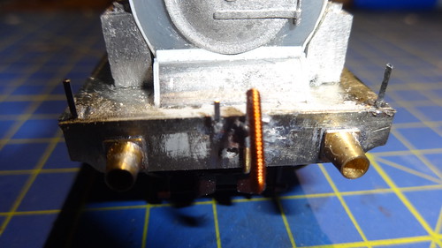
Also added was the tank vents which are in front of the cab running up the edges of the cab from the tanks to pretty much up to the roof line. Made from 1mm brass rod, bent in to shape, a small 1mm hole drilled in the tank top to take the rod, and soldered to the front of the cab.
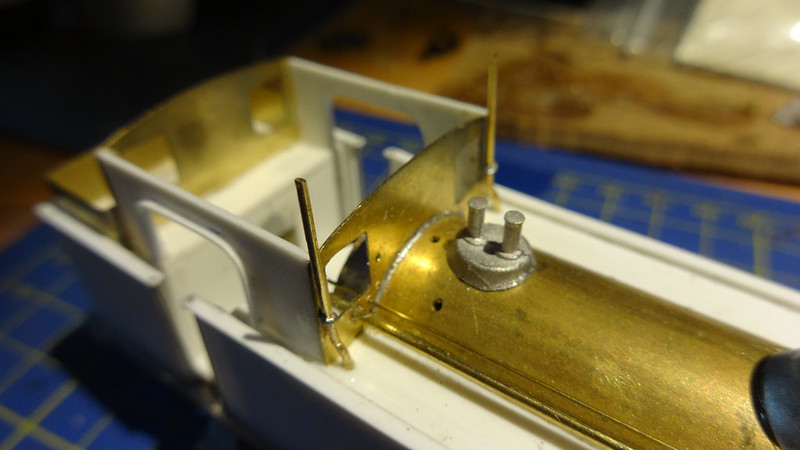
The small tank filler caps were also fitted at this point using a 3mm drill bit I drilled the hole in the top of the tank around about the middle, these were secured in position by a small drop of superglue gel. You can also see a number of holes drilled for the various pipe work and whistle position.
While on the pipe theme, I also flipped the loco upside down and added the sand pipes at the front and from the rear boxes, I also added the pipe to the vacuum pipe on the front buffer beam.
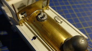 
Overall the model is coming together quite nicely and is running to plan and to time, which overall is pretty good, and generally looks like and has the character of the a Metropolitan E-Class.
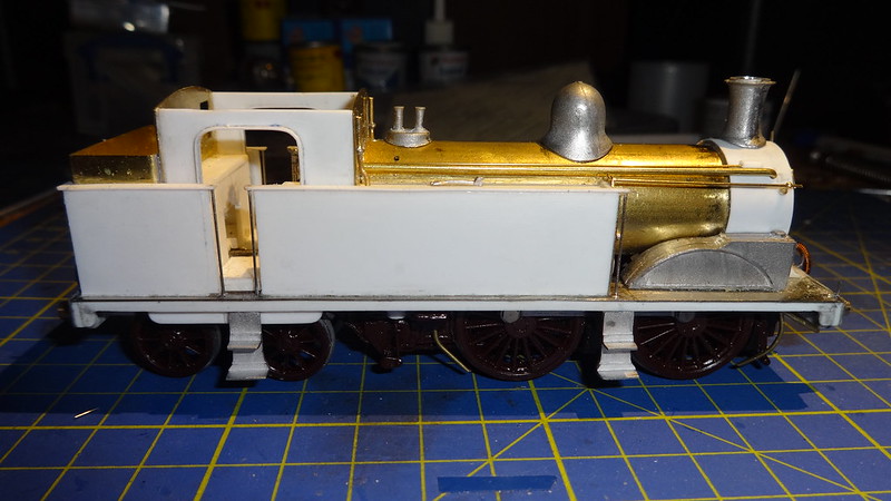
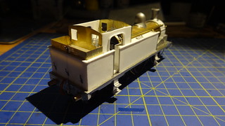 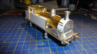
More later on in the week.
|
|
Deleted
Deleted Member
Posts: 0
|
Post by Deleted on Jun 15, 2015 2:02:49 GMT
Updates: Turning my attention while the body shell is relatively complete, I moved on to the cab details and interior. The back head was again a casting spare from SE Finecast which was quite handy, I made a regulator handle from sratch using a few bits and pieces of off cuts. This was the first item to receive a bit of paint, as this will go in to a video showing how I paint back heads not just for kits but for some RTR models too. The paints used were, Halfords Primer as a base coat, Matt Black x2 coats, Humbrol 55, 34 white, 174 red, and Acrylic 16 Gold. 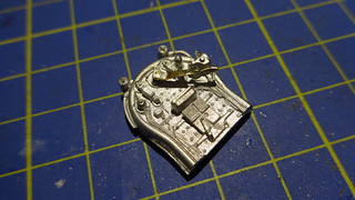 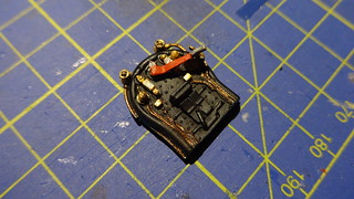 Inside the cab, I have constructed the hand brake column and handle from 0.45mm wire and an old handbrake casting, which I drilled a small hole in the base and glued in the wire. I also made the holder for the wire from some off cuts of brass. The reverser handle was made out of a spare wheel from a ballast hopper which was from a Cambrian kit, a similar method to the brake handle below. 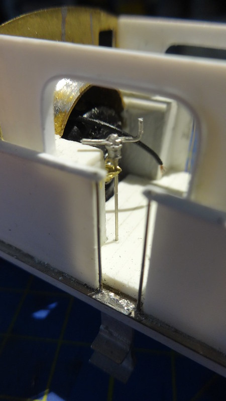 Now on to the final bits and pieces to go on to the model before cleaning and priming. The boiler bands were added around the boiler using plasticard (10/000) cut in to strips about 1.5mm wide using super glue gel which seems to hold it quite well I attached the boiler bands working from measurements and pictures to gauge their position. Also added was the fire iron holders on the left tank, which were made from the same split pins seen above used for the lamp irons on the front and rear of the model. The pins were cut to around 15mm long, 10mm is left straight and then using pliers I bent a U shape in the remaining section to hold the fire iron tools. 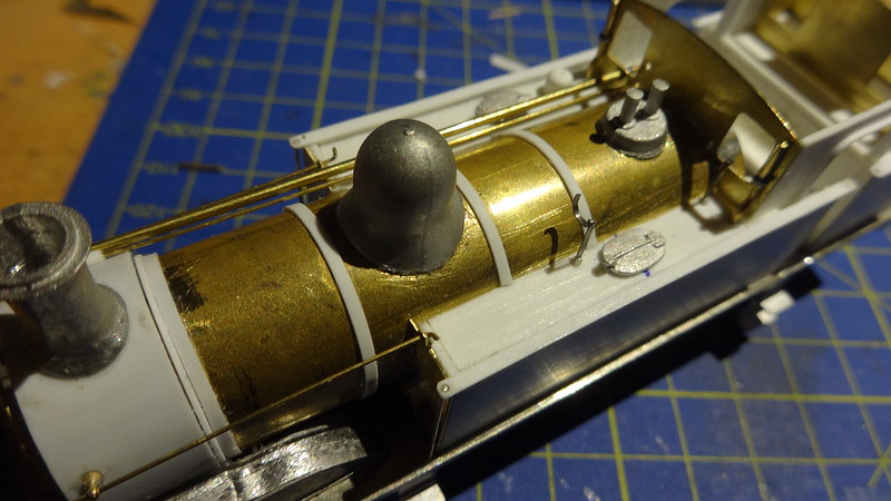 The model is then cleaned, any excess glue or filled cleaned up and flat back so I have a nice smooth surface, the primer I will be using be plastic based Halfords Grey primer.several light coats are applied and any issues such as depressions in the surface or holes or gaps will be filled, leveled, and then the process is repeated until the surface is to a level you are happy with. 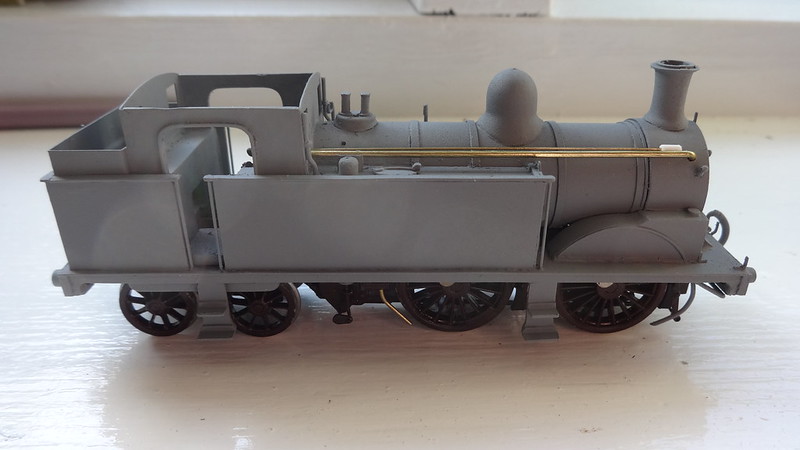 There shall be another small update tomorrow night, on a subject that came up on the forum recently about rivet surface detail. Anyway more on that tomorrow. |
|
Deleted
Deleted Member
Posts: 0
|
Post by Deleted on Jun 16, 2015 22:44:03 GMT
Once you are happy with the surfaces, then a bit more detailing can be done. My original plan was to place brass sheet along the sides of the water tanks, then adding rivet detail using a centre punch, but I wasn’t happy with the test results so I changed my approach. I have used some transfers before which have resin drops to represent rivets, I have used them before on other builds and found them very good. They come in various sizes, and spacings and are produced by Archers in the USA, and available from DCC supplies. The work in exactly the same way as water slides which is nice and simple, the transfer sheets are not cheap but they are good and do get you what you want and that's simple and effective rivet detail. The rivet transfers were applied to the water tanks, top of the bunker plate, and the smoke-box. 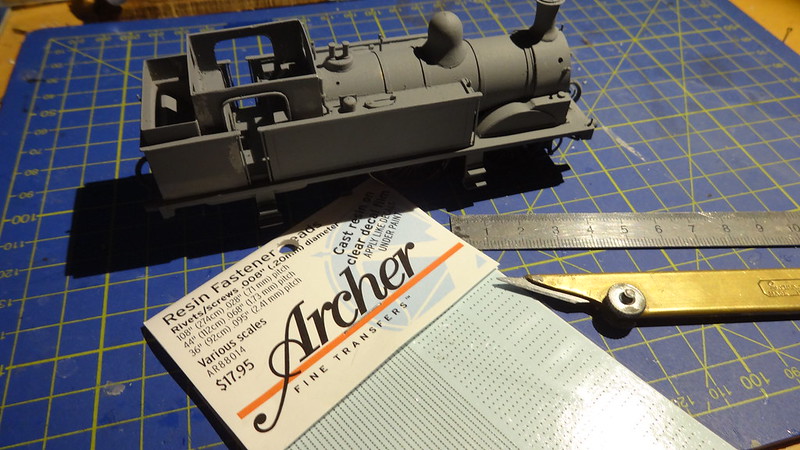 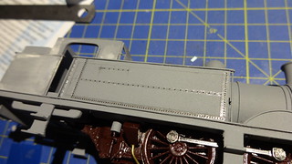 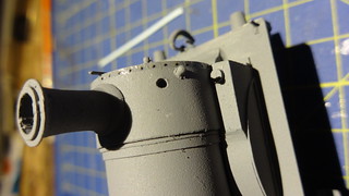 After the transfers have been applied it was back to the paint shop and some more light coats of primer, just to seal in the rivets so they won’t be disappearing or pealing off when the model is handled at this moment in time.  Now on to some colour! I originally brought some London Underground Maroon, but found this too dark, more like Met 1’s paint / livery prior to its overhaul, with it’s polished brass dome. I was more after a bit more red as it appears on the picture above, I had alread in my paints, LT red which was from Pheonix cherry paint range (C163) which I got for L150 when I was changing bits and pieces on that model... when testing the paint it was in my view too red, so i managed to add some black to darken the red and to tone it down a bit. In photos of Met 1 the colour does vary a lot depending the light, as you can see from the image at the start of the topic the red is very red in bright sun light. When its undercover or underground it does look deeper... So it’s quite a challenge to try and replicate that on a model. I got to a point where I was reasonably happy, it is quite a bit darker than it was but to me it looks ok.  The LT red coats had around 3 – 4 coats as well as a buffer beam red. Then the black got added which was Humbrols Satin black (85) any brass or shiny bits mainly around the splashers were picked out with Humbrol acrylic (16). All the hand rails and pipe work were removed prior to paint being applied. 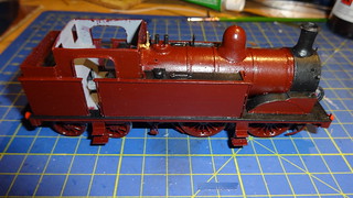 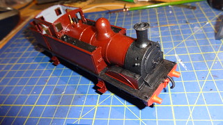 More on Wednesday. |
|
|
|
Post by metroland on Jun 18, 2015 7:43:21 GMT
Nice work there bluebell87
|
|
Deleted
Deleted Member
Posts: 0
|
Post by Deleted on Jun 20, 2015 22:23:04 GMT
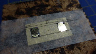
Thanks Metroland, suppose I better finish it off  Now for the expensive part, the transfers, as I think we all know London Underground is a bit of a specialist interest in modelling, which generally means if you are going model it, it’s generally going to cost quite a bit. Transfers are difficult to get hold of, and I only know of one supplier which I have used in the past for the Metropolitan Coaches, and thats Radley models. For Metropolitan one I ordered 2 sheets, one for the lining which was mainly for a Pannier, and the second for Numbers, logos, and lettering, which cost about £35. The transfers are water slides, so easy to apply, and straight forward. I started with the lining first, for the running plate, steps, cab, and splashers I used HMRS yellow lining sheet, which matched the yellow on the Radley transfers, and luckily I had to hand! 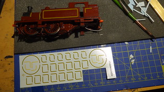 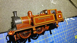 Before more finishing off, a little bit more building, although some parts are present on the above pictures, on the chassis the guard irons were missing on the front, and took me a little while to sort out how to attach them, I would use some more brass off cuts, cut and filed to shape, on the chassis there is a plastic keeper plate which for me is lucky and runs to the front of the chassis and comes up around the sides. The guard irons I managed to bend the tops over to hook over the plastic keep plate, when I was happy, i primed them and then glued them in place.  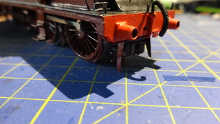 Some may of noticed that so far through out this, there's been no mention of a roof for the cab, don’t worry it’s not going to be a convertible, or is it? I think most of you know I like detail, and sometimes I go a little to far, on Metropolitan 1, there are 2 sliding vents in the roof, some of you may remember some RTR manufactures had these on their locos... well I’m bringing it back.The roof made from the same brass sheet as before, cut to size, and the sides bent up and then a strip soldered along the side to create the gutters for water run off, and then marked out where the sliding vents should go, this done, the same method for making the windows was used to make the holes for the vents. 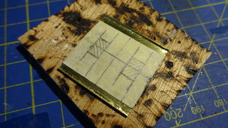 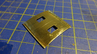 The roof was genitally curved to create the profile of the roof, on the actual roof there is a main beam of metal going down the center, which I will also add to keep the profile or curve of the roof. Again using the same brass sheet i scored the curve in to the brass and filed it to match. This was then solded on to the center of the roof, which you can see had been marked on the above image. The roof was then test fitted to make sure the profile was still correct after soldering.  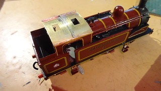 Next was to put in a locator on the underside so the roof would locate in to the right place, using some 1mm plasticard, I cut out the shape of the cab, and then cut a 3mm in from the outside edge to allow an opening for the vents, this was then glued to the underside of the cab roof, this worked pretty well, and fitted very well. 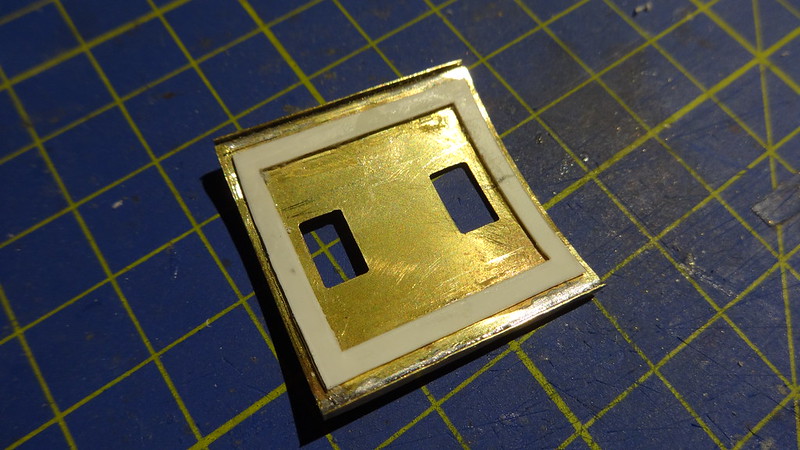 Next was the tricky bit, to create sliding vents for the roof, which would be fun. on the roof I found in some off cuts in my spares box of some chemically blackened brass, 0.5mm wide and just long enough to make 4 runner strips on the top of the roof. These were glued to the roof just in case i needed to move them later. The vent slides were made up of 2 brass pieces cut from a brass sheets, with plasticard in the center which was about 1mm thick and some brass sheet underneath so it there was some play for it to move. The roof was primed with Halfords Grey primer, and was partially assembled to check the vents moved and it was still OK. The roof was then sprayed with Halfords Matt black to finish.  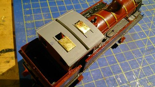 Back to the transfers and all of them had now been applied and were sealed in with a couple of coats of acrylic varnish by Vellejo, which also lifts the colour of the paint making it brighter. 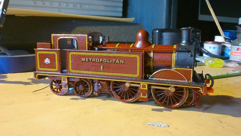 Back to the chassis at this point I wanted to test everything to make sure everything worked, the chassis tested fine, as I mentioned way back in the topic I always planned to add pickups to the bogie, so that’s where this is where it happens. Using some copper clad electrical board, I mounted this to the underside of the bogie, I scored through the foil on the top of the board to isolate each side, so they do not create a short. A small hole was drilled in the bogie to guide the wires through for the 2 pin micro plug brought from DCC Supplies. The pickups are made from Phosphor Bronze strip, and soldered to the copper clad board, The 2 pin plug and its wires run up through the bogie housing to the side of the motor, where the other connector is located.  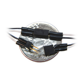 The bogie is attached by a machine screw, with a spring, the nut that holds it all together is insulated from the bronze pick up strips. I went back to detailing the underside of the model, as it looks a bit bare around the steps, and some pipe work needs adding. I use some copper wire (0.6mm) for the pipe work, which is bent to shape with some pliers. Met 1 is a little unusual when its comes to pipe work as some of the pipes are insulated or have what i think are rubber pipe joiners. To try and replicate this, I wrapped the pipes in very small strips of masking tape, which i wrapped around the brass, and then soaked it in super glue. This seems to work quite well and look pretty good to my eye 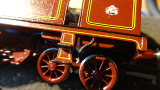 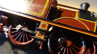 All the back head and cab parts have now been installed, 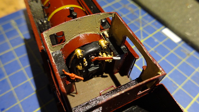 As some will know, Met 1 has some brass window frames on the cab, which I also wanted to replicate, it took a little time to find a provider, lucky the Narrow Planet who are extremely kind and helpful managed to etch me 4 window frames to my specification for this model... and I am very pleased with them. The rear 2 frames, need protective bars over the windows as they face the bunker, i did this by soldering some 0.45m wire over the windows. The pipe work in front of the cab has been made using a hand rail holder, and using some 0.1mm copper wire bent to shape. The whistle some may recognize, I used an old casting of a whistle from a kit and drilled a 1mm hole in the center, I have some spare turned brass whistles believe this one is off an A4 it was shortened, and the base turned and then glued in position. 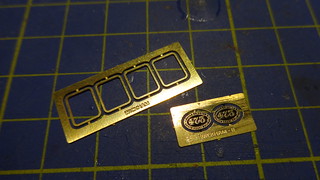 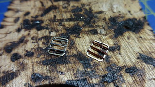 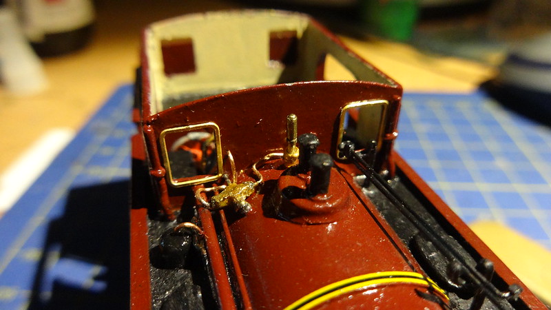 Anyway with everything on including the glazing in the windows, it was now time to glue the roof on and give it a run. 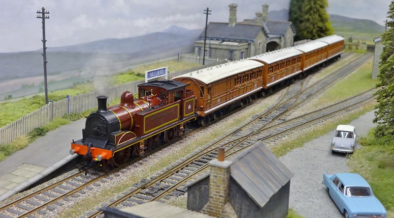 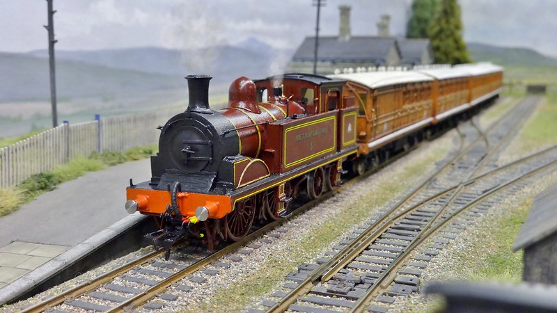 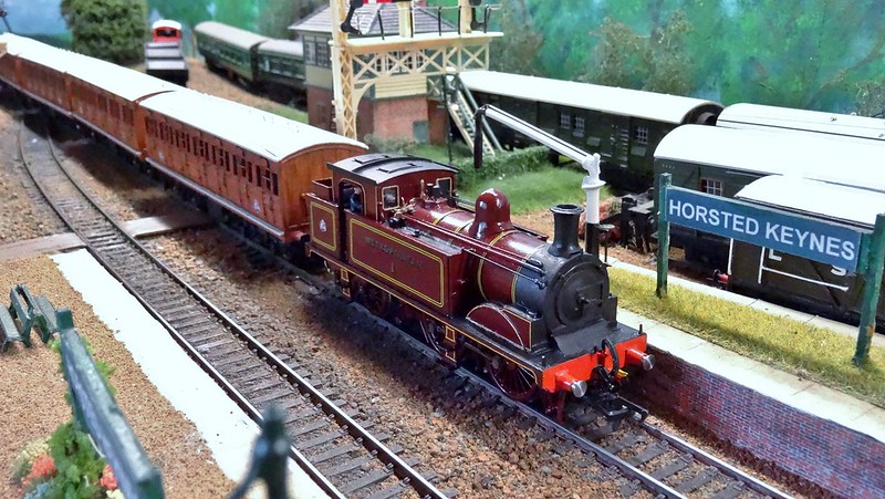 Anyway thanks for following and viewing, hope some of you may find it useful, and give you some new ideas, and inspire you to do bigger and better things. |
|
metman
Global Moderator
5056 05/12/1961-23/04/2012 RIP
Posts: 7,421
|
Post by metman on Jun 21, 2015 0:18:16 GMT
Top work. I too will be modelling Met No 1 however mine will be L44.....
|
|
|
|
Post by The Tram Man on Jun 21, 2015 10:11:03 GMT
Wow, that is some great work there, Bluebell.
|
|
Deleted
Deleted Member
Posts: 0
|
Post by Deleted on Jun 21, 2015 12:57:09 GMT
Thank's all much appreciated, I have a little bit of test footage as well where it ran a couple of weeks ago on our Clubs test track.
|
|
Deleted
Deleted Member
Posts: 0
|
Post by Deleted on Jun 21, 2015 13:27:31 GMT
wow. Great to see it from start to finish.
|
|
|
|
Post by twihlet on Jun 24, 2015 16:50:28 GMT
These Chesham/Bluebell coaches are great. Some of the above comments show how important it is to maintain the information paper-trail when rolling stock is rebuilt, refurbished, restored or otherwise modified. The Met itself started the confusion by designing them for loco haulage, then converting them to EMU, then some back to steam haulage after WW11. The mention of Joe Brook-Smith took me back. In the mid '60s he got some way to producing a Met Bo Bo in 4mm to be made by the vacuum forming process. He estimated that the price of a couple of sides and ends would be around 7/6d (37 1/2p). This was way outside my budget at the time, so I lost interest. Does anyone know if anything did happen with this project?
|
|
Deleted
Deleted Member
Posts: 0
|
Post by Deleted on Jun 26, 2015 10:11:44 GMT
Thank you for your comments guys, I apologize for the delay in reply, sadly someone decided pruning a forum was an excellent idea and deleted my account for the second time in 6 months.... maybe best not to touch the forum.
I heard about this Twihlet in regard to the vacuum forming of also some of these Chesham coaches were made the same way, could be by the same guy? It came up last year on RMweb, that the forms still exist and some do have some of the formed models, so possibly did go ahead but doesn't look as though it got very far.
|
|
metman
Global Moderator
5056 05/12/1961-23/04/2012 RIP
Posts: 7,421
|
Post by metman on Feb 5, 2016 0:01:20 GMT
Unlocked for you Bluebell87.
|
|


