DrJimi
Virtual District Line construction engineer and arborist
Posts: 365
|
Post by DrJimi on Nov 28, 2007 17:24:14 GMT
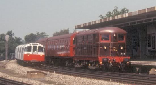
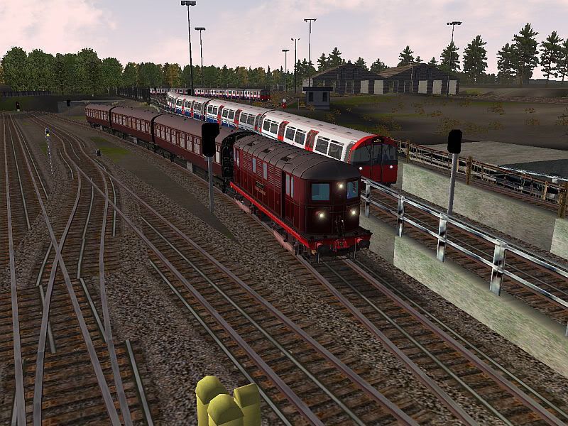
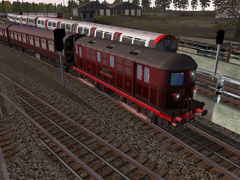
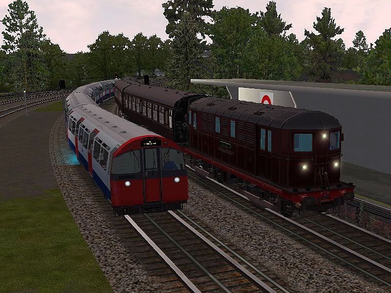
The team has always wanted to try and replicate this loco:  Here's a couple of screenshots of our version road testing on the DR: APPROACHING ACTON TOWN FROM SOUTH EALING AS A COCKFOSTERS 73TS WAITS ON THE BANK  1200HP PULLING 3 BEAUTIFUL MAROON MK1 COACHES (COURTESY OF IAN)  AN ATTEMPT TO REPLICATE THE PREVIOUS REAL PHOTO - PASSING CHISWICK PARK AS THE 73TS OVERTAKES  You must have had a great view of that Doc! More news as it happens. /Jimi |
|
|
|
Post by onetrain on Nov 28, 2007 20:02:28 GMT
Really good Jimi Keep it up as it looks Fanstatic  . Will it have a cab made for it becuase as this is one of my many Favourite Ex-LU train and might make a great Bve train  . |
|
Deleted
Deleted Member
Posts: 0
|
Post by Deleted on Nov 29, 2007 8:13:18 GMT
Cab construction is taking place at this moment. I am at present trying to resource more photographic material to work from but rest assured i will try my best. I've downloaded the tech docs for RS and are attempting to build this one following the new Rail Sims cab construction guidelines on modeling and texturing. This could well be the first loco with a 3D Working Cab for RS that the Virtual District Team produces. Good thing is, it will still be usable in MSTS aswell.
Darren.
|
|
|
|
Post by onetrain on Nov 29, 2007 8:43:17 GMT
Ok, Sounds Brillant Darren, Good Luck with the Construction.
|
|
Deleted
Deleted Member
Posts: 0
|
Post by Deleted on Dec 2, 2007 19:36:29 GMT
Excellent replication of the loco.... think we need a Track Walk though...
|
|
|
|
Post by tubeprune on Dec 3, 2007 7:48:56 GMT
What great screenshots. I wonder - the TC set has 4 coaches and there is a cab at each end of it. Is it your intention to include it as part of the model? Would you have a historical version with Dreadnoughts?
|
|
DrJimi
Virtual District Line construction engineer and arborist
Posts: 365
|
Post by DrJimi on Dec 7, 2007 2:56:17 GMT
Apologies for the late reply - been busy with the new RailSim.
Artery - Track walk? As in checking for clearance? If so, yes. We're also in process of re-laying all route tracks with real 3D 4-rail trackwork, more realistic points, and all new tracks east of West Ken. As part of that I'm checking for clearance and adjusting bridges, platforms, etc.
TubePrune - I realized shortly after I posted that I have 1 coach too few. The released consist will be accurate. I regret I'm unfamiliar with Dreadnoughts but will research. Our intent is to have very detailed 3D cabs at each end, and maybe also model the interior (battery area, etc.) to some degree. With the planned RailSim version we can have a real 3D cab and can look around it (and thus see through the cab back wall door). We will also be able to "change ends" thus driving from either cab.
Thank you all for your interest! If anyone has any releated refernce material regarding the control/motoring/braking systems, loco weight, power, etc. I'd greatly appreciate it. Also any photos of the cab and its internals would greatly help Darren get his cab model accurate. We're putting a lot of effort into this one and hope to do justice to this fine loco.
Thanks, Jimi
|
|
|
|
Post by tubeprune on Dec 7, 2007 8:28:21 GMT
TubePrune - I realized shortly after I posted that I have 1 coach too few. The released consist will be accurate. I regret I'm unfamiliar with Dreadnoughts but will research. Plenty of info available here if you need it for a historical version. Loco weight 61.5 tons (UK tons!) Motor type MV 339 - 4 per loco. Motor Rating 1 hour: 300hp Motor Rating continuous: 210hp Gear Ratio: 23:57 Wheel dia 3ft 7 1/2ins new Max tractive effort: 22,600lbs There is a full description of the traction control system in "Electric Trains" Vol II by WA Agnew, Virtue 1937. There are fold out diagrams of the interior of the loco too. There are lots of copies about. |
|
DrJimi
Virtual District Line construction engineer and arborist
Posts: 365
|
Post by DrJimi on Dec 8, 2007 0:34:42 GMT
Exactly what I was looking for - thank you TubePrune! That confirms the 1200hp total (max) I had read elsewhere. I'll try with a nominal 900hp to fine-tune the physics. Armed with all that data I can convert to SI units and determine Max force (kN), etc. and now knowing the weight I can figure the inertia/momentum/rail friction and figure the Davis equation values.
Would you know if the control system is similar to, say, the Battery loco controller and resistance grid (i.e no RPA nor notching relays, etc.)? Does #12 by now have Windyhouse or an earlier brake system? Any idea of brake force or G-force deceleration would also be useful (or anecdotal 'it can stop from XXmph in XX metres/furlongs/rods/poles/perches')?
Thanks again - we always try for accuracy in our models. This has helped greatly.
EDIT: from the above (converting to SI), 61.5 short tons = 55.8t (metric). It appears we have total motor power of 670KW, and the TE would require a force of 124kN (at 0.553m wheel radius and 23:57 gear ratio). Gears provide about 2.5 times torque multiplication. I supply MSTS physics specs with power, force and wheel radius. Off to edit and test. I bet I can get wheel slip...
Best regards, Jimi
|
|
|
|
Post by tubeprune on Dec 8, 2007 9:48:27 GMT
Jimi,
I am sending you a pm with a scan of the power circuit for Loco 12 in original condition. It was run by a standard Met Vickers electro-magnetic contactor group with a four position master controller. There were two complete sets for the loco, one for each bogie.
As for braking, I can only assume that now the loco has to comply with LU standard 1.15m/s/s maximum service braking rate and 1.3m/s/s emergency straight line curve. I recall No 12 having a BR type M6a brake valve and two distributors fitted when she began working with BR coaches. I'm not sure what she has now but it is likely to be similar.
The original locos had CBE vacuum brakes (2 x 24inch cylinders) as well as Westinghouse with two triple valves and 2 x 12" brake cylinders. I can't find a reference to the percentage weight braked. I used to have a catalogue of blueprints of all Met stock with those sort of details but it was "removed by persons unknown" many years ago. I know a number of them existed then including photocopies. I wonder if any readers here have a copy with the data?
|
|
DrJimi
Virtual District Line construction engineer and arborist
Posts: 365
|
Post by DrJimi on Dec 8, 2007 15:16:58 GMT
Thank you again! I can certainly model to those max deceleration rates, and I'll check my notes on that brake control equipment. Thanks to your PM'd diagram I located the info re the Met locos in WA Agnew Vol 2. I will read further and take notes!
Thanks, Jimi
|
|


