DrJimi
Virtual District Line construction engineer and arborist
Posts: 365
|
Post by DrJimi on Nov 24, 2006 3:19:11 GMT
I'm trying to get the physics right on our MSTS Battery Loco. I know (from tfl data) it weighs 62t. I know max speed is about 30mph. What isn't listed is stuff like Power and Tractive Effort. I have a good physics model for the SSL and Tube stocks for the consists they pull, so if I knew approximate relative power/force compared to an SSL DM I could calc it from there. So a couple of questions...
1. How many Turbots (nominal 40t loaded) does/can a single Battery pull?
2. Is that a typical consist, or are there always 2 Batteries top/tailed?
3. If so, how many can/do 2 locos pull? On what gradient?
I'm testing them exiting Lillie Bridge and right now can maintain 10mph (1 loco + 3 Turbots) up the exit bank. On the flat I can eventually hit 30mph. Braking with that load (180t) is "interesting"...
4. Do the Batteries use EP or EP+Rheo?
5. Is a 59TS control setup about right (separate brake/controller)?
Any info or pointers greatfully appreciated!
/Jimi (shunting TransPlant consists for a change)
|
|
towerman
My status is now now widower
Posts: 2,879
|
Post by towerman on Nov 24, 2006 4:14:16 GMT
No EP/Rheo on battery locos,used to be Westinghouse,but was changed a few years back for something similar but more up to date,the name of the system escapes me,maybe some other member knows.Battery locos do have a seperate brake and traction controller but the traction controller is different to passenger stock has shunt,series,series-parallel and parallel.BTW,Happy Thanksgiving.
|
|
|
|
Post by trainopd78 on Nov 24, 2006 12:37:44 GMT
There is also no through control line between locos, so one driver is required per loco with comms between them. The brake pipe is of course continuous throughout the train with the leading driver in control of the handle.
|
|
towerman
My status is now now widower
Posts: 2,879
|
Post by towerman on Nov 24, 2006 19:53:11 GMT
When they were fitting out the Brixton Extension,the works trains then all used through control,as I was a fitter on the Victoria Line then we had to remove the jumpers before the train entered the possession and when it returned,refit them and do a full control test.
|
|
|
|
Post by trainopd78 on Nov 27, 2006 18:09:53 GMT
I suppose it must depend on the waggons in between the locos.
|
|
Deleted
Deleted Member
Posts: 0
|
Post by Deleted on Jan 8, 2007 15:54:57 GMT
What was the shape of the reveser key for these loco's. The slot looks nothing like that used on the stock of today although it does look the same as the CO/CP. Also what positions (refering to a clock face) would the throttle be in for Shunt, Series, Series/Parallel and parallel. Information i need for my next MSTS Cab. Thanks.
Darren.
|
|
towerman
My status is now now widower
Posts: 2,879
|
Post by towerman on Jan 8, 2007 20:06:38 GMT
It was the same key that was used on passenger stock.
|
|
|
|
Post by tubeprune on Jan 8, 2007 20:42:13 GMT
It was the same key that was used on passenger stock. Yes, it was used in the squat, fat GEC button type controller. It was a real pig to operate. The air brake was originally Westinghouse No 5 valve. I have no idea how you would simulate it. How do you simulate a lag between the blow from the equalising valve and the response of each vehicle? |
|
DrJimi
Virtual District Line construction engineer and arborist
Posts: 365
|
Post by DrJimi on Jan 8, 2007 23:49:03 GMT
It can be done TubePrune. I did a basic Westinghouse implementation for our 59TS and 38TS stocks. Appropriate paremeter values can be set for each 'car' as to equipment present, relevant pressures, etc. Kuju actually did quite a good job of some of the brake modeling. You can even add gauges to watch (or test in my case) what pressures are where (main res, Eq res, train pipe, etc. There's also a very comprehensive data display that a recent 'BIN' add-on has provided, such that you can also monitor (say) the end car and thus see brake lag between the cars. A few folks on here who have Westinghouse experience though my model was quite close - including the appropriate 'hisses' and other air noise FX. Fun to do - made a change from Westcode and Rheo stuff.
Best, Jimi
|
|
|
|
Post by tubeprune on Jan 9, 2007 7:27:12 GMT
A few folks on here who have Westinghouse experience though my model was quite close - including the appropriate 'hisses' and other air noise FX. Fun to do - made a change from Westcode and Rheo stuff. My hat off to you and your fellow designers DrJimi. I am not a sim user but, with a genuine Whse, I might be tempted. As for battery locos, the original set up was a loco at each end of the train and no through control or brake. After couple of incidents (Caledonian Road and Dollis Hill) they did add through brake and control. I can't remember if they did it together or separately. They then changed the Whse brake valve for a BR style proportional valve and a 2-pipe braking system with distributors on each vehicle. I wonder if anyone knows when this was done. The 1964-73 Battery locos are fitted with four WT54D traction motors rated at 112kW for one hour using 600v. On battery, the voltage is 320. The gear ratio is 16:65. Don't forget also that Battery locos have hand notching controllers. The train weights and lengths permitted vary for each line and location. The presently published regulations show some strange restrictions e.g. the maximum load south of Neasden (Met) is 280t with 2 locos, whereas the Jubilee max load is 392t. If you take 300t as the max load you could go almost anywhere but I suspect it is rarely used. Train length should not be more than 90m to allow access almost anywhere. |
|
DrJimi
Virtual District Line construction engineer and arborist
Posts: 365
|
Post by DrJimi on Jan 9, 2007 18:43:17 GMT
Excellent info sir - thank you, I will print that out for reference. Armed with that new info (motor power, etc.), I can calculate tractive effort and see how close my physics model is. If I'm figuring this right, the example 280t would be 2 x loco (60t each) + 4 x Turbots (nominal 40t each). If so, that works very nicely for a prototypical consist! Or 6 Turbots for a 360t total. I'll re-check the total train length for each and see. I now have something new to test/research this evening...  Thanks much, Jimi (latent physicist) |
|
towerman
My status is now now widower
Posts: 2,879
|
Post by towerman on Jan 9, 2007 20:41:16 GMT
I think the Westinghouse brake was replaced in the early 90's,they were given the same system as the ill fated 85 locos.
|
|
|
|
Post by District Dave on Jan 9, 2007 20:53:28 GMT
(Adding nothing to the technical discussion here.....) I think I find myself waiting in anticipation of this to try for myself! Maybe now that I've replaced my graphics card (having suffered for probably two years with a fault without realising it until the old one died on Saturday) it seems that sims are worth reinstalling Starting to rub hands and search for the discs......... |
|
Deleted
Deleted Member
Posts: 0
|
Post by Deleted on Jan 10, 2007 12:09:25 GMT
Where is the shunt position on the throttle as i can't see it on my pic.  Cheers Darren. |
|
|
|
Post by tubeprune on Jan 10, 2007 14:27:03 GMT
Where is the shunt position on the throttle as i can't see it on my pic. There is no "Shunt" position as such. It is the first notch on the controller. ISTR there were 9 notches for each sector, series, series-parallel and parallel. The last notch is "Full......" whatever position you are in. All electric trains were like this once. The sleet locos were the same but they only had series and parallel and the parallel was blocked by a stop on the controller. |
|
Deleted
Deleted Member
Posts: 0
|
Post by Deleted on Jan 10, 2007 15:09:11 GMT
You mean i have to model 27 positions for this throttle  |
|
|
|
Post by tubeprune on Jan 10, 2007 17:55:13 GMT
You mean i have to model 27 positions for this throttle It depends on how accurate you want it to be. Drivers are told not to hold a particular intermediate position for more than 15s for fear of overheating the resistors. These locos do not have automatic acceleration. Can you simulate varying weights and adjust the power of the loco accordingly for each position? There is a weight table for all the different engineer's vehicles. It's in the ETS of the WRM. Those who have access to the LUL intranet and standards sites will know what I mean. |
|
DrJimi
Virtual District Line construction engineer and arborist
Posts: 365
|
Post by DrJimi on Jan 10, 2007 18:52:11 GMT
Fascinating!! So the operator is effectively doing the work of the (later employed) RPA gubbins manually. Yes Darren, it looks like Off + 3 groups of 9 notches in terms of animation images needed. Or we could reduce that somewhat, as I can do position interpolation in the cab view code to make the motion look smooth. Maybe 5 for each group? Meaning 16 total frames? 5 per would actually work real nice for the physics/controller code. Looks like there's 'gaps' between the groups too. I can use the same brake code as for the 38TS so we get EP (or Windyhouse if needed). Based on TP's info I'm now much closer to realistic power/torque/accel/braking physics, using a 6-car consist (L-T-T-T-T-L) AT 280t total. That's more than twice the weight of a typical LUL 6-car SSL consist. Makes the braking "an interesting experience" EDIT: With regard to TP's question re modeling weights, etc.. Yes - the weight of each 'car' is defined, along with many other attributes like CG, aero drag, imputed inertia and momentum, rail friction, etc. A pretty comprehensive physics model. So as part of that I can define the attributes of a driving motor car (of any type) as to it's 'motor' values (power, tractive effort, and a bunch of other stuff) that let me simulate the effects of an electric motor with "LUL controls" quite well. And yes, the motor controller notches simulate defined percentages of voltage (as a result of reomoving resistances), as best we can within MSTS; although the exact effect of (say) series vs. parallel can't be exactly modeled. But I get it close. The sim takes all of that into account (effect of car weights, drag, etc.) which thus affect inertia, accel, momentum, grades, decel, braking, etc. I have good models for D78, 73TS, C69, 59TS, 38TS (which in some cases only differ in defined weights) - but this Battery Loco is a whole new beast and I'm having to 'work at the physics' to get it to behave realistically. Which I find great fun, of course As a side note, I'm fortunate to have the 2 volume set of WA Agnew's "Electric Trains" in excellent condition for a 1937 issue! Vol 1 describes the motors and control systems in great detail (including bridge transition circuitry and RPAs). I'll have to re-read and see if he also discusses these 'manual' types of controller... Best Jimi (writing the C69 Op Guide) |
|
|
|
Post by tubeprune on Jan 10, 2007 21:16:26 GMT
As a side note, I'm fortunate to have the 2 volume set of WA Agnew's "Electric Trains" in excellent condition for a 1937 issue! Vol 1 describes the motors and control systems in great detail (including bridge transition circuitry and RPAs). I'll have to re-read and see if he also discusses these 'manual' types of controller... Agnew has a description of the BTH manual system used on the District Line 1920 Stock. Aslo, look at the LMS 1932 Watford Stock description also because it shows a manually controlled GEC set-up. The GEC battery loco version was similar but with the additional series-parallel bit inserted. Thinking about it again, I am not sure you should have the train weight at so high a level. I would suggest starting at 150t. Perhaps, if you get a control set-up, you can play with the weights until it feels right. Is that possible? Do we have anyone on the forum who has driven a ballast train recently? |
|
DrJimi
Virtual District Line construction engineer and arborist
Posts: 365
|
Post by DrJimi on Jan 10, 2007 23:46:05 GMT
Cool - I'll re-read Mr Agnew this evening, and thank you for the pointers. I figured the consist weight, as LUL says a Battery is 62t, and a Turbot is 19t empty, 49t max (so I picked 40t as nominal). Given consists are apparently top/tailed we're at approx 120t + Turbot weight. So an L-T-T-L would be about 200t, etc. Now armed with your data re the motors, I should be able to calc tractive effort (and other related stuff) and figure what 2 locos should be able to haul. As far as lengths, the BT is 17m, the Turbot 16m, so a 4-car is 66m and a 6-car is 98m (over 90m, per your previous comment re accessability). 5-car would be 82m long and weigh 240t (about twice a 6-car D78 weight). I'm quite game to start at, say, 2 Turbots (200t total train weight) and work the physics from there, if that is what you'd recommend. At this point I'm just trying to get a Battery to behave close to realistic physics-wise. I doubt that the bulk of Joe Public would know if it was off (if so), but we try to get our LUL stocks as close as available data and MSTS physics will allow. Of course, that's because I'm anal and consider this a simulation, not a game ;D Incidentally, here's a few screenies of the locos (23 and 45) in the sim: 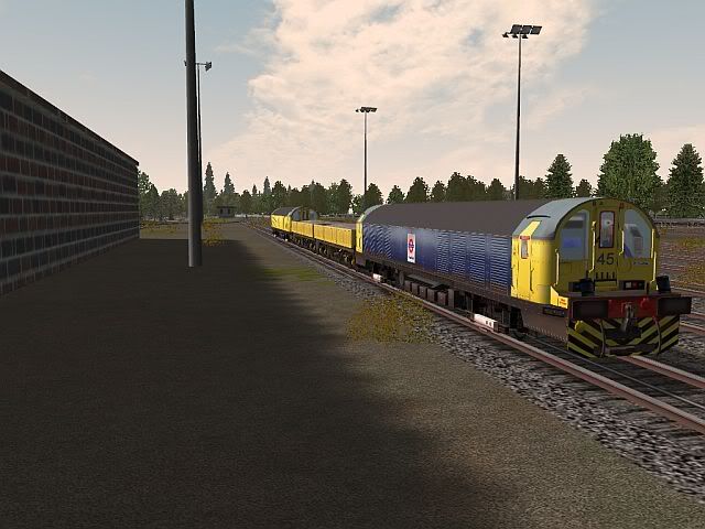 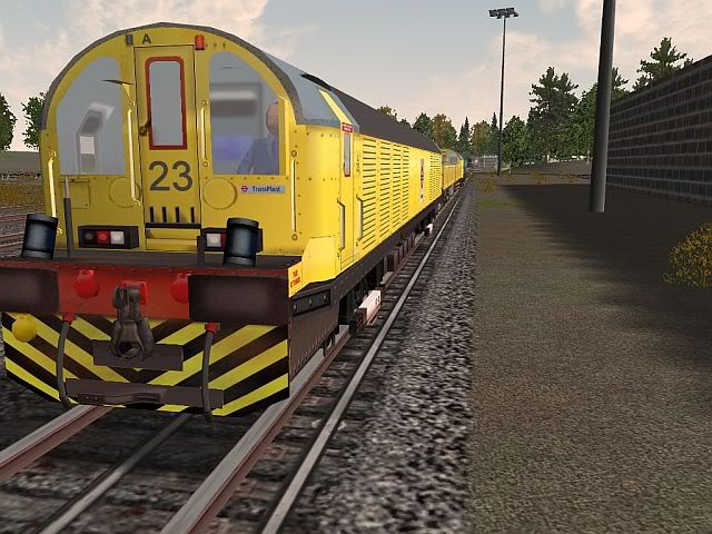 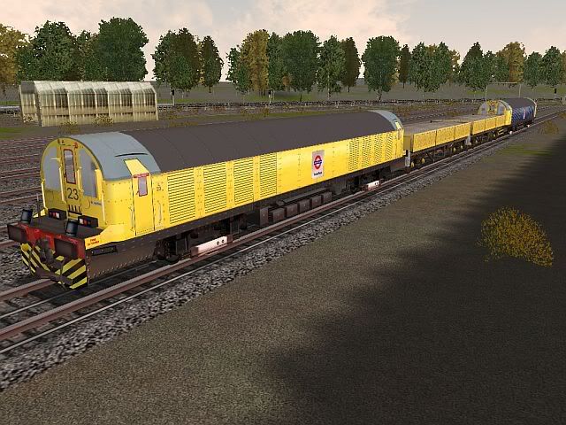 The operator is a 'familiar figure' who I believe recently noted he'd like to drive one of these in the sim  Another related question - I notice a rotating beacon on the front of the cab. Under what conditions is this active? As I have 2 light switches to use in the sim, lights1 could be the front/rear lights and lights2 could be the beacon. Or is it active all the time? Thanks for any insights. Best, Jimi |
|
Deleted
Deleted Member
Posts: 0
|
Post by Deleted on Jan 11, 2007 8:08:14 GMT
I figured the consist weight, as LUL says a Battery is 62t, and a Turbot is 19t empty, 49t max (so I picked 40t as nominal). Given consists are apparently top/tailed we're at approx 120t + Turbot weight. So an L-T-T-L would be about 200t, etc. Now armed with your data re the motors, I should be able to calc tractive effort (and other related stuff) and figure what 2 locos should be able to haul. As far as lengths, the BT is 17m, the Turbot 16m, so a 4-car is 66m and a 6-car is 98m (over 90m, per your previous comment re accessability). 5-car would be 82m long and weigh 240t (about twice a 6-car D78 weight). Sorry,that's just flown completely over my head I'll stick to getting the cab as best i can. So the controller moves in a clockwise direction and must be able to rotate almost 360 degrees. Do you have to go through accelaration in all the notches on the controller or can you move the handle directly to the first notch on the series/parallel sector if running light or for any other reason. Darren. |
|
|
|
Post by tubeprune on Jan 11, 2007 8:25:15 GMT
The pictures are excellent. I'm sorry, I do not know about the beacon light. I can't find a reference to it in the WRM. Perhaps someone else can help.
I am not sure if all battery locos have the new Davis & Metcalfe brake valve. They operate differently from the Westinghouse valve. There is a shutdown position on the handle and I think there is a proportional graduated release facility. I have never used one so I can't help further. It is a standard main line locomotive brake valve. I assume someone will have modelled it. Perhaps there is a forum which will be worth contacting.
|
|
Deleted
Deleted Member
Posts: 0
|
Post by Deleted on Jan 11, 2007 9:30:58 GMT
|
|
DrJimi
Virtual District Line construction engineer and arborist
Posts: 365
|
Post by DrJimi on Jan 11, 2007 17:02:35 GMT
No worries Daren - I'm just tryign to figure how much 'oomph' we need to haul about 200t around ;D And get it to stop!
Tubeprune - thank you again. I thin I'll model it as an EP system with graduated release (ala our 59TS and C69). Except with more braking force, of course. Sufficiently realistic and not too hard for our users to manage.
Darren - re the 'winding it up'... The limit (I'm pretty certain) is going to be how much current is drawn for a specific condition (weight) and notch position. The whole idea of the later RPA stuff was to 'notch up' automatically (e.g. the 9 or whatever resistor bank posiitons per grouping) as current fell below a certain value, thus maintaining current within a specific range. With this controller the Op is doing all that manually. So - yes, with a light load I perceive they'd be able to wind it up to maybe 'full series' from rest. Anyone know if an Ammeter is in the cab? Would seem like an important gauge to me (plus we can model it as a working gauge). So we could still use (say) 5 positions per group (e.g. Series1...Series5, etc.) and get enough control granularity. Maybe as few as 3 would work to give enough. As Tubeprune noted, its down to how realistic/accurate we want to be. The controls code side of it is no problem no matter how many total notches we decide to use.
Re the consist pics you noted, I see some with 4, 6 and as many as 9 Turbots attached. That large one would be over 400t total! It appears these locos can really haul.
|
|
|
|
Post by tubeprune on Jan 11, 2007 17:31:09 GMT
DrJimi, There were no ammeters in the cab in my day - before D & M brake conversion.
It was normal to accelerate by selecting the first notch, holding it for a while and then going to the last notch of that set. You would then hold it at that notch until the speed balanced, then select the first notch of the second group, hold it, last notch, hold it etc.
I might have a traction curve for a WT54 motor somewhere. I'll try to find it.
|
|
DrJimi
Virtual District Line construction engineer and arborist
Posts: 365
|
Post by DrJimi on Jan 12, 2007 0:26:25 GMT
Got it! That helps enormously. We could then just 'model' the (positions of) the first and last notch in each group (plus Off), so 7 notches total. The Op Guide could then describe those notches as prototypical use. Simplifies our implementation, but looks realistic. If you do happen to have the traction curve, I'd certainly appreciate looking at it at your convenience.
Darren - does this help you in determining the positions for the animation frames?
Many thanks, Jimi (off to tweak the physics again)
|
|
|
|
Post by tubeprune on Jan 12, 2007 7:31:13 GMT
DrJimi, if you went from notch 1 to notch 9 too quickly, the CB would trip out. You would have to reset it and start again, on the move.
|
|
Deleted
Deleted Member
Posts: 0
|
Post by Deleted on Jan 12, 2007 7:47:04 GMT
Hi Tubeprune/Jimi
7 notches would simplify things allot, but there is no hassle to animate as many positions as is required. Once i can get a legend onto the controller top i will line up the handle from above with whatever positions we decide to use (Off, First/Last position of each group).
Does MSTS do trip current thresholds, i don't think I've come across it. If not, shame as that would have really come into it's element on this loco.
Tubeprune, To reset on the move, i take it you would put the handle back to off, reset and then take her up slowly until you find the pulling point.
Darren.
|
|
DrJimi
Virtual District Line construction engineer and arborist
Posts: 365
|
Post by DrJimi on Jan 12, 2007 18:09:02 GMT
Tubeprune - understood sir. That's why I wondered if an Ammeter was present to warn of imminent excess, as clearly over-current would pop the breaker. As Darren notes, we'll use as many animated positions as neede to give a realistic representation. I'd also love to model any attendent crackles, sparks, pops and bangs ;D
Darren - I'm not aware of an over-current trip, but will investigate again. I know current draw is modeled correctly (based on related real-time factors), and there is a cab gauge type to display it (analog or digital).
|
|
|
|
Post by tubeprune on Jan 12, 2007 20:02:38 GMT
Tubeprune, To reset on the move, i take it you would put the handle back to off, reset and then take her up slowly until you find the pulling point. Darren. Exactly. |
|